
- Home
- BMW 3 Series
- E46
- Electrical equipment
- Equipment and devices
- Troubleshooting Electrical Circuits — Basics
Troubleshooting Electrical Circuits — Basics (BMW 3 Series E46)
Note: Before you begin, please read the warnings given in paragraph "Safety first!" and in paragraph 1 of this chapter. The procedures described in this chapter apply only to electrical circuits and should not be used to test electronic circuits of systems (such as anti-lock braking system), and especially those related to electronic control units.
Warning. The electrical system of the BMW 3 Series is very complex. Most of the control units are connected to a "common bus" system, from which they receive signals from various sensors and can exchange information with each other. For example, when a certain gear is engaged in an automatic transmission, this signal is transmitted via the "common bus" to the engine control unit. Even though the gear is changed by the transmission control unit, the engine control unit changes the ignition timing, reducing the engine output to ensure smooth changes in vehicle speed during gear changes. Since the control units are connected to the "common bus", these units cannot be checked with a multimeter in the usual way. To facilitate troubleshooting in the circuits, the control units have a built-in self-diagnosis function. The control units store fault codes that help to determine the location of the fault. Special equipment is required to read these moves (trouble code reader or scanner).
Basic information
1. A typical electrical circuit consists of electrical components - switches, relays, motors, fuses, fuse links or circuit breakers - connected by wiring and connectors to each other and to the battery and chassis. To help you troubleshoot electrical circuits, wiring diagrams are provided at the end of this manual.
2. Before you begin troubleshooting an electrical target, study the relevant wiring diagram and gain a thorough understanding of the components in the circuit. Finding possible sources of trouble is easier if you make sure that other components in the circuit are working properly. If several components or circuits fail at the same time, the fault may be in their common fuse or ground connection.
3. Electrical circuit faults usually arise from simple causes such as: loose or corroded connection contacts, poor grounding, failure of a fuse or fuse link, or a faulty relay (for a detailed description of how to test a relay, see paragraph 3). Before you begin checking the circuit parts, inspect the condition of all fuses, wires, and connectors in the faulty circuit. Use the wiring diagrams to determine which connections need to be checked to locate the fault.
4. The list of basic tools for troubleshooting electrical circuits is quite simple and includes: a tester or voltmeter (for some tests, a 12-volt test light with wires can also be used): battery powered indicator (also called a break indicator); ohmmeter (for measuring resistance); battery with a set of control wires; a jumper wire, preferably with a fuse, that can be used to bypass wires or suspect electrical components under test. Before you begin troubleshooting with instruments, determine the points to connect them to using a wiring diagram.
5. To find the source of an intermittent fault in the electrical wiring (usually caused by a poor connection or damaged insulation), you can simply move the wires. If the contact in the circuit appears and then disappears, then the source of the fault is in this place of the electrical wiring. This method of checking can be used along with any others described in the following subparagraphs.
6. Besides bad contacts, there are two other main types of faults: open circuit and short circuit.
7. When the target is broken at any point, the component's current supply stops, and consequently its operation stops, although the break in the circuit does not cause the fuse to fail.
8. Short circuits are usually caused by a breakdown in the insulation of electrical wiring. When wires touch each other or a wire touches the body. A short circuit usually blows the fuse of the corresponding circuit.
Detecting chain breaks
9. To locate an open in the circuit, connect one of the tester leads to the negative battery terminal or to a good ground.
10. Connect the other test lead to the terminal in the circuit being tested, preferably the one closest to the battery or fuse.
11. Turn on the circuit. Note that some circuits are only closed when the ignition switch is in a certain position.
12. Presence of voltage (what does the light of the control lamp or the reading of the voltmeter indicate), means that the section of the circuit between the corresponding connector and the battery is OK.
13. Continue checking the remaining sections of the circuit in the same manner, gradually moving away from the battery.
14. If a point where there is no voltage is found, then the section between this point and the previously checked point is faulty. Check it in more detail to find the fault. Most faults are caused by corrosion, breakage or loose contacts.
Short circuit detection
15. Before testing a circuit for a short circuit, disconnect the load from the circuit (load - components that consume power, such as light bulbs, motors, heating elements, etc.).
16. Remove the appropriate circuit fuse and connect the tester or voltmeter leads to its terminals.
17. Turn on the circuit, keeping in mind that some circuits are closed when the ignition switch is in a certain position.
18. Presence of voltage (what does the light of the control lamp or the reading of the voltmeter indicate) confirms a short circuit.
19. If there is no voltage during this test, but the fuse blows when the load is connected, this indicates an internal fault in the load.
Ground fault detection
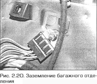
20. The negative terminal of the battery is connected to the "ground" - the engine-transmission-body unit. Most consumers of electrical energy are connected only to the positive wire, and the negative conductor is the metal of the body (Fig. 2.20). This means that the body mass is part of the circuit. In this regard, poorly tightened connections can lead to a partial or complete break in the circuit. And this can cause dim lighting (especially if another circuit is connected that uses the same ground point), slowing down the rotation of engines (such as a windshield wiper motor or a cooling fan motor) and the effect of one circuit on the operation of another. Note that many vehicles use flexible grounding bars to connect to the body of units that do not have direct metal-to-metal contact with it, such as, for example, the engine-transmission unit mounted on rubber mounts.
21. To check the reliability of the component ground, disconnect the battery and connect one lead of the ohmmeter to a point with a reliable ground. Connect the other lead of the ohmmeter to the point of the component being tested. The ohmmeter should register zero resistance; otherwise, check the component ground connection as follows.
22. If you suspect that the ground connection is broken, disassemble this connection, clean both the contact point on the body and the wire tip (or the mounting surface of the unit body) to the metal. Remove all traces of dirt and corrosion. Use a knife to scrape off the paint to ensure a clean metal-to-metal connection. Assemble the connection and tighten the fasteners carefully. If the ends of the wires have tips, install serrated washers between the tip and the body to ensure a secure connection. To prevent corrosion of the connection after it has been restored, lubricate the outside with technical petroleum jelly or silicone grease (or periodically spray it with special moisture-protective agents).
(This article is based on data from the website: bmwman)
This article is available at russian, bulgarian, belarusian, ukrainian, serbian, croatian, romanian, polish, slovak, hungarian
Article verified: Ilyinsky Matvey
Share information:
Previous articles
БМВ E46: Equipment and devices
Next articles
Similar articles on other types of BMW cars:
General information about troubleshooting electrical circuits BMW 5 Series E28 (1981-1988)
Troubleshooting electrical equipment BMW 5 Series E39 (1995-2003)
Troubleshooting electrical equipment BMW 7 Series E32 (1986-1994)
Engine Electrical System Specifications BMW 7 Series E38 (1994-2001)
Decoding of electrical circuits BMW X3 E83 (2003-2010)
Checking electrical systems BMW X5 E53 (1999-2006)
Link in different formats to this page
Visitor comments
No comments yet
- General information
- Manual
- Maintenance
- Power unit
- Engine repair
- Cooling system
- Power system (gasoline)
- Injection system (gasoline)
- Fuel system (diesel)
- Exhaust system
- Ignition system
- Charge and launch systems
- Transmission
- Car gearbox
- Clutch and drive shafts
- Chassis
- Brake system
- Suspension front and rear
- Steering
- Body
- Body care and repair
- Exterior
- Interior
- Electrical equipment
- Troubleshooting
- Lighting and signaling
- Equipment and devices
- Heater and air conditioner
- Electrical circuits
- General information
- Manual
- Repair on the road
- Weekly checks
- Maintenance
- Troubleshooting
- Power unit
- 4 cylinder engines
- 6 cylinder engines
- Engine overhaul
- Cooling and heating
- Fuel and exhaust system
- Starting and charging system
- Ignition system
- Transmission
- Clutch
- Mechanical gearbox
- Automatic gearbox
- Cardan and drive shafts
- Chassis
- Brake system
- Wheel suspension
- Steering
- Body
- Exterior
- Interior
- Electrical equipment
- Equipment and devices
- Electrical circuits
- General information
- Maintenance
- Power unit
- Engine repair
- Cooling system
- Ignition system
- Supply system
- Fuel injection system
- Exhaust system
- Transmission
- Clutch
- Car gearbox
- Front and rear axle
- Chassis
- Steering
- Brake system
- Body
- Exterior
- Interior
- Electrical equipment
- Heating system
- Equipment and devices
- Power devices
- Electrical circuits
- Power unit
- M10/M20 engine
- M40 engine
- Ignition system
- Lubrication system
- Cooling system
- Supply system
- Fuel injection
- Exhaust system
- Transmission
- Clutch
- Manual gearbox
- Front axle
- Rear axle
- Chassis
- Steering
- Brake system
- Body
- Exterior
- Interior
- Electrical equipment
- Heating system
- Equipment and devices
- Electrical circuits
- General information
- Specifications
- Operation and maintenance
- 4-cylinder engine
- Engine repair
- Cooling and lubrication system
- Supply system
- Ignition system
- 6-cylinder engine
- Engine repair
- Cooling and lubrication system
- Supply system
- Fuel injection system
- Ignition system
- Transmission
- Clutch
- 4-speed manual gearbox
- 5-speed manual gearbox
- Automatic gearbox
- Cardan and rear axle
- Chassis
- Steering
- Front suspension
- Rear suspension
- Brake system
- Electrical equipment
- Equipment and devices
- Electrical circuits