
Table of contents: Checking the lamps ↓ Checking the electric motor ↓ Checking the operation of switches…↓ Checking lamp switches and electric…↓ Checking switches-sensors ↓ Checking the relay ↓ Checking the changeover relay ↓ Checking the windshield wiper motor ↓ Checking the windshield wiper motor ↓ Checking the brake light ↓ Checking the rear window heating ↓
- Home
- BMW 7 Series
- E32
- Electrical equipment
- Equipment and devices
- Troubleshooting electrical equipment
Troubleshooting electrical equipment (BMW 7 Series E32)
If you suspect a fault in electrical equipment, you need to carry out diagnostics slowly and systematically, without missing obvious causes.
The first step should always be to check the fuse that protects the circuit in question. The location of the fuses is indicated in the glove box and on the back of the right-hand trunk trim.
Replace the blown fuse, and after turning on the corresponding consumer, check whether the fuse burns out again. In this case, you need to eliminate the cause of the burnout. Most often, this is a short circuit, i.e. somewhere the wire or contact of the positive voltage supply and the ground are connected.
Step two: If the lamp does not light or the electric motor does not rotate when the fuse is in good condition, then you need to check the voltage supply.
Remove the bulb and check the integrity of the filament. If it is burnt out or the glass bulb does not fit tightly in the base, then the bulb needs to be replaced.
The lamp can be checked for proper operation by connecting it directly to the battery using auxiliary wires. The polarity of its connection does not matter. You need to make sure that the lamp contacts are clean and free of corrosion and, if necessary, clean them and the contacts in the socket. If the lamp does not light, it must be replaced.
If the lamp is OK, then you need to insert it into the socket and turn it on. If the lamp does not light, you need to check the voltage supply using a test lamp. To do this, connect one of its wires to a high-quality ground (bare metal), and the other one to the voltage supply contact in the socket. If the control lamp lights up, but the lamp being tested does not, then its connection to the ground is broken. You can run an auxiliary wire to the ground.
If there is no voltage on the current-carrying wire, i.e. the control lamp does not light, then you need to check the switch and the voltage supply circuit.
Many functions in a car are performed by electric motors. Electric motors operate the window lifts, sunroof, central locking, etc. Each electric motor is controlled by a switch.
Check and, if necessary, replace the fuse for the corresponding motor.
If the fuse blows again, there is a short circuit somewhere.
To determine the serviceability of the electric motor, you need to connect its contacts using auxiliary wires (diameter about 2 mm) directly from the AB, observing the polarity. All electric motors in the car operate from 12 V. If the engine now operates normally, then the fault is in the voltage supply circuit. If the engine rotates slowly, then its contact brushes may be worn out and need to be replaced.
If the engine is running, then you need to use the diagram to determine which wires supply voltage to it, how the switch works, and whether the ignition should be on.
Check the motor current lead with a test lamp with two sharp contacts to pierce the wire insulation if necessary. The connecting contacts of electric motors are marked as standard.
Motors that rotate in two directions, such as power window motors, have two contacts for supplying positive voltage:
If there is no voltage on the engine, then the voltage supply circuit is faulty. In this case, you need to use electrical equipment diagrams to find the fault. Due to the high current consumption, relays are often built into the voltage supply circuit, the testing of which is described below. If everything is OK in the power supply circuit, check the switch.
If there is a break in the wire, it is easier to install a new wire than to look for the break in the old one.
Most electrical consumers are switched on and off by switches that are operated manually. However, there are also switches that operate automatically. These include, for example, switches for oil pressure and brake fluid level warning lights.
The job of any switch is to close and open a current circuit. Some switches open the ground circuit, others open the positive voltage supply circuit.
Remove the switch.
A simple switch has two contacts for wires, one of which is supplied with voltage constantly, and the other - after the switch is triggered. There are also switches with several contacts (switches). The operation diagrams of such switches, i.e. the supply of voltage to them, are indicated in the electrical equipment diagrams. If necessary, turn on the ignition.
Use a test lamp to check if there is voltage supplied to the switch. If there is, (the lamp is on), then turn off the switch and check if voltage appears on its output contact. If it does, the switch is working properly.
If there is no voltage at the input contact, then there is a break in the supply circuit, which must be eliminated, if necessary, by installing a new wire.
The following are related to the sensor switches: switches for oil pressure, brake fluid and coolant levels.
Connect the ohmmeter to the switch contacts, disconnecting the wires from them.
When the switch is closed, the ohmmeter should show a resistance close to 0 ohms.
The easiest way to check the functionality of the coolant and brake fluid level indicator switches is to disconnect the wire from the switch with the ignition on and connect this wire to ground. If the indicator light on the instrument panel lights up, the switch is faulty.
The oil pressure warning light switch works differently: when the engine is not running, its contacts are closed (the control lamp is on), and when a certain oil pressure is reached, the switch opens.
Many circuits have relays installed. A changeover relay works like a switch: when the consumer's switch is tripped, the (manually activated), then the relay receives a command to supply voltage to the consumer. Of course, it is possible to supply current to the consumer from the battery directly through the switch, but for consumers consuming high current, the relay is switched on so as not to overload the switch or to provide the shortest path for supplying voltage. In addition to such switching relays, there are functional relays, for example, a windshield wiper/washer relay.
When the corresponding consumer is switched on, the relay is triggered, i.e. under the influence of the control current, the coil inside the relay closes the contacts through which the main, "working" current passes, which goes to the consumer.
The easiest way to check the relay's functionality is to replace it with a known good one. A car does not always have a spare relay. If it does not, then you need to perform the following operations. The following contact designations are given for serially installed relays.
Remove the relay from its socket.
Turn on the ignition and the corresponding switch.
Check with a voltmeter for voltage at contact 30 in the relay socket by connecting it between ground and contact 30. If there is no voltage, check the circuit supplying voltage to it from the battery and eliminate the break.
Make a jumper wire by stripping two ends of insulated wire.
Connect this jumper between pins 30 and 87 (relay output contact). In this case, the operation of a working relay is simulated. The location of the contacts is usually indicated on the relay itself or on the relay socket. If the consumer is triggered when the jumper is installed, then it can be concluded that the relay is not working.
If the consumer does not work, then you need to check the connection of the consumer to the ground. Then you need to check the wires going from contact 87 to the consumer.
If necessary, replace the relay with a new one.
The windshield wiper motor is located in a recess under the windshield. To check, you need to remove the cover.
Engine contact designations:
First of all, you need to find out what is faulty: the motor or the power supply circuit. To do this, do the following:
Disconnect the plug from the wiper motor.
Using two auxiliary wires, connect the battery to the windshield wiper motor: connect the positive wire to contact 53 or 53v, connect the negative wire to contact 31. Now the windshield wiper motor should work at speed 1 or 2. If this is not the case, then the motor or the corresponding circuit is faulty.
If the brake light does not come on, you need to check the fuse.
If the fuse is intact, check the bulbs and replace them if necessary.
Check the brake light switch by removing the cover above the pedals. Remove the plug from the switch.
Turn on the ignition.
Jumper the contacts in the brake light switch plug with a short auxiliary wire. If the brake light now lights up, the switch is faulty and must be replaced.
If it doesn't light, check the lights.
When the rear window heating is switched on, the area with the heating threads is freed from fogging and ice after a while.
If there is a fault, first check the fuse.
If the fuse is OK, check the tightness of the connectors on the left and right sides of the rear window, clean off any corrosion if necessary.
If the rear window defroster still does not work, check the wires, switch and relay.
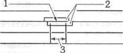
1 - damaged wire;
2 - adhesive tape;
3 - area to be repaired.
If the heating wires are damaged, conductive silver paste should be used to restore contact. Before applying it, the damaged areas should be cleaned with solvent or alcohol.
Cover the damaged area on both sides with adhesive tape and apply silver paste with a thin brush.
The paste should dry for about 24 hours at 25°C. You can use a hair dryer. At +150°C the paste dries in about 30 minutes.
Do not turn on the glass heating until the paste is completely dry. Do not use gasoline or other mineral solvents to clean the parts.
The first step should always be to check the fuse that protects the circuit in question. The location of the fuses is indicated in the glove box and on the back of the right-hand trunk trim.
Replace the blown fuse, and after turning on the corresponding consumer, check whether the fuse burns out again. In this case, you need to eliminate the cause of the burnout. Most often, this is a short circuit, i.e. somewhere the wire or contact of the positive voltage supply and the ground are connected.
Step two: If the lamp does not light or the electric motor does not rotate when the fuse is in good condition, then you need to check the voltage supply.
Checking the lamps
Remove the bulb and check the integrity of the filament. If it is burnt out or the glass bulb does not fit tightly in the base, then the bulb needs to be replaced.
The lamp can be checked for proper operation by connecting it directly to the battery using auxiliary wires. The polarity of its connection does not matter. You need to make sure that the lamp contacts are clean and free of corrosion and, if necessary, clean them and the contacts in the socket. If the lamp does not light, it must be replaced.
If the lamp is OK, then you need to insert it into the socket and turn it on. If the lamp does not light, you need to check the voltage supply using a test lamp. To do this, connect one of its wires to a high-quality ground (bare metal), and the other one to the voltage supply contact in the socket. If the control lamp lights up, but the lamp being tested does not, then its connection to the ground is broken. You can run an auxiliary wire to the ground.
If there is no voltage on the current-carrying wire, i.e. the control lamp does not light, then you need to check the switch and the voltage supply circuit.
Checking the electric motor
Many functions in a car are performed by electric motors. Electric motors operate the window lifts, sunroof, central locking, etc. Each electric motor is controlled by a switch.
Check and, if necessary, replace the fuse for the corresponding motor.
Note: Electric motors of window lifts and sunroof are usually protected by automatic devices that switch off when overloaded and switch on again after a while. When switching on again, the cause of the overload must be eliminated. This may be ice on the glass or dirty sunroof or glass guides.
If the fuse blows again, there is a short circuit somewhere.
To determine the serviceability of the electric motor, you need to connect its contacts using auxiliary wires (diameter about 2 mm) directly from the AB, observing the polarity. All electric motors in the car operate from 12 V. If the engine now operates normally, then the fault is in the voltage supply circuit. If the engine rotates slowly, then its contact brushes may be worn out and need to be replaced.
If the engine is running, then you need to use the diagram to determine which wires supply voltage to it, how the switch works, and whether the ignition should be on.
Check the motor current lead with a test lamp with two sharp contacts to pierce the wire insulation if necessary. The connecting contacts of electric motors are marked as standard.
- contact 32 - ground connection;
- contact 33 - positive voltage supply.
Motors that rotate in two directions, such as power window motors, have two contacts for supplying positive voltage:
- contact 33L - for left rotation of the motor;
- contact 33R - for right rotation of the motor.
Note: The windshield wiper motor has its own contact designations.
If there is no voltage on the engine, then the voltage supply circuit is faulty. In this case, you need to use electrical equipment diagrams to find the fault. Due to the high current consumption, relays are often built into the voltage supply circuit, the testing of which is described below. If everything is OK in the power supply circuit, check the switch.
If there is a break in the wire, it is easier to install a new wire than to look for the break in the old one.
Checking the operation of switches (switches)
Most electrical consumers are switched on and off by switches that are operated manually. However, there are also switches that operate automatically. These include, for example, switches for oil pressure and brake fluid level warning lights.
The job of any switch is to close and open a current circuit. Some switches open the ground circuit, others open the positive voltage supply circuit.
Checking lamp switches and electric motors
Remove the switch.
A simple switch has two contacts for wires, one of which is supplied with voltage constantly, and the other - after the switch is triggered. There are also switches with several contacts (switches). The operation diagrams of such switches, i.e. the supply of voltage to them, are indicated in the electrical equipment diagrams. If necessary, turn on the ignition.
Use a test lamp to check if there is voltage supplied to the switch. If there is, (the lamp is on), then turn off the switch and check if voltage appears on its output contact. If it does, the switch is working properly.
If there is no voltage at the input contact, then there is a break in the supply circuit, which must be eliminated, if necessary, by installing a new wire.
Checking switches-sensors
The following are related to the sensor switches: switches for oil pressure, brake fluid and coolant levels.
Connect the ohmmeter to the switch contacts, disconnecting the wires from them.
Note: Switches that are screwed into the cylinder block usually do not have a ground connection wire - the switch housing serves this purpose.
When the switch is closed, the ohmmeter should show a resistance close to 0 ohms.
The easiest way to check the functionality of the coolant and brake fluid level indicator switches is to disconnect the wire from the switch with the ignition on and connect this wire to ground. If the indicator light on the instrument panel lights up, the switch is faulty.
The oil pressure warning light switch works differently: when the engine is not running, its contacts are closed (the control lamp is on), and when a certain oil pressure is reached, the switch opens.
Checking the relay
Many circuits have relays installed. A changeover relay works like a switch: when the consumer's switch is tripped, the (manually activated), then the relay receives a command to supply voltage to the consumer. Of course, it is possible to supply current to the consumer from the battery directly through the switch, but for consumers consuming high current, the relay is switched on so as not to overload the switch or to provide the shortest path for supplying voltage. In addition to such switching relays, there are functional relays, for example, a windshield wiper/washer relay.
Checking the changeover relay
When the corresponding consumer is switched on, the relay is triggered, i.e. under the influence of the control current, the coil inside the relay closes the contacts through which the main, "working" current passes, which goes to the consumer.
The easiest way to check the relay's functionality is to replace it with a known good one. A car does not always have a spare relay. If it does not, then you need to perform the following operations. The following contact designations are given for serially installed relays.
Remove the relay from its socket.
Turn on the ignition and the corresponding switch.
Check with a voltmeter for voltage at contact 30 in the relay socket by connecting it between ground and contact 30. If there is no voltage, check the circuit supplying voltage to it from the battery and eliminate the break.
Make a jumper wire by stripping two ends of insulated wire.
Connect this jumper between pins 30 and 87 (relay output contact). In this case, the operation of a working relay is simulated. The location of the contacts is usually indicated on the relay itself or on the relay socket. If the consumer is triggered when the jumper is installed, then it can be concluded that the relay is not working.
If the consumer does not work, then you need to check the connection of the consumer to the ground. Then you need to check the wires going from contact 87 to the consumer.
If necessary, replace the relay with a new one.
Note: If the fault occurs from time to time, it is most likely related to the relay. In this case, the contact comes off and connects randomly, and the relay also works irregularly. You can knock on the relay body when it does not work. If the relay works after knocking, it is faulty and is subject to.
Checking the windshield wiper motor
The windshield wiper motor is located in a recess under the windshield. To check, you need to remove the cover.
Engine contact designations:
- contact 31 - ground connection (throughout the entire electrical system);
- contact 53 supplies voltage for the first speed of the windshield wiper;
- contact 53a supplies voltage for the initial position of the windshield wiper: there is voltage on the motor from the sliding contact as long as the windshield wiper is in the non-working state, i.e. when the driver turns off the windshield wiper;
- contact 53v supplies voltage for the second speed of the windshield wiper;
- via contact 53e, the windshield wiper motor is braked during the reverse stroke after switching off, so that the windshield wiper arms do not jump out of their original position.
Checking the windshield wiper motor
First of all, you need to find out what is faulty: the motor or the power supply circuit. To do this, do the following:
Disconnect the plug from the wiper motor.
Using two auxiliary wires, connect the battery to the windshield wiper motor: connect the positive wire to contact 53 or 53v, connect the negative wire to contact 31. Now the windshield wiper motor should work at speed 1 or 2. If this is not the case, then the motor or the corresponding circuit is faulty.
Checking the brake light
If the brake light does not come on, you need to check the fuse.
If the fuse is intact, check the bulbs and replace them if necessary.
Check the brake light switch by removing the cover above the pedals. Remove the plug from the switch.
Turn on the ignition.
Jumper the contacts in the brake light switch plug with a short auxiliary wire. If the brake light now lights up, the switch is faulty and must be replaced.
If it doesn't light, check the lights.
Checking the rear window heating
When the rear window heating is switched on, the area with the heating threads is freed from fogging and ice after a while.
If there is a fault, first check the fuse.
If the fuse is OK, check the tightness of the connectors on the left and right sides of the rear window, clean off any corrosion if necessary.
If the rear window defroster still does not work, check the wires, switch and relay.
1 - damaged wire;
2 - adhesive tape;
3 - area to be repaired.
If the heating wires are damaged, conductive silver paste should be used to restore contact. Before applying it, the damaged areas should be cleaned with solvent or alcohol.
Cover the damaged area on both sides with adhesive tape and apply silver paste with a thin brush.
The paste should dry for about 24 hours at 25°C. You can use a hair dryer. At +150°C the paste dries in about 30 minutes.
Do not turn on the glass heating until the paste is completely dry. Do not use gasoline or other mineral solvents to clean the parts.
This article is available at russian, bulgarian, belarusian, ukrainian, serbian, croatian, romanian, polish, slovak, hungarian
Article verified: Sevastyanov Nikolay
Share information:
Previous articles
БМВ E32: Equipment and devices
Next articles
Similar articles on other types of BMW cars:
Troubleshooting electrical equipment BMW 3 Series E46 (1998-2006, petrol)
Scheme 1. General electrical equipment starting with 1990 models 316i… BMW 3 Series E30 (1982-1994)
Troubleshooting electrical equipment BMW 5 Series E39 (1995-2003)
Electrical equipment diagram for cars «525» and «528» BMW 5 Series E12 (1972-1981)
Car electrical equipment — equipment and tools BMW X3 E83 (2003-2010)
General information about on-board electrical equipment BMW X5 E53 (1999-2006)
Troubleshooting electrical equipment BMW 3 Series E46 (1998-2006, petrol)
Scheme 1. General electrical equipment starting with 1990 models 316i… BMW 3 Series E30 (1982-1994)
Troubleshooting electrical equipment BMW 5 Series E39 (1995-2003)
Electrical equipment diagram for cars «525» and «528» BMW 5 Series E12 (1972-1981)
Car electrical equipment — equipment and tools BMW X3 E83 (2003-2010)
General information about on-board electrical equipment BMW X5 E53 (1999-2006)
Link in different formats to this page
Visitor comments
No comments yet
- General information
- Introduction to guide
- Manual
- Maintenance
- Power unit
- Engine M60/1, M60/2 (petrol)
- M62 engine (petrol)
- M57 engine (diesel)
- M67 engine (diesel)
- Cooling system
- Fuel system (petrol)
- Fuel system (diesel)
- Exhaust system
- Ignition and control systems
- Charge and launch systems
- Transmission
- Clutch
- Mechanical gearbox
- Automatic gearbox
- Cardan and drive shafts
- Chassis
- Brake system
- Front suspension
- Rear suspension
- Steering
- Body
- Exterior
- Interior
- Electrical equipment
- Equipment and devices
- Lighting
- Heating and air conditioning
- Electrical circuits
- General information
- Care and maintenance
- Power unit
- Minor engine repair
- Engine overhaul
- Lubrication system
- Cooling system
- Ignition system
- Supply system
- Injection system (petrol)
- Injection system (diesel)
- Exhaust system
- Transmission
- Clutch
- Manual gearbox
- Automatic gearbox
- Cardan gear
- Rear axle and shafts
- Chassis
- Front suspension
- Rear suspension
- Steering
- Wheels and tires
- Brake system
- Body
- Body elements
- Electrical equipment
- Equipment and devices
- Electrical circuits