
First you need to make sure that the starter turns the engine crankshaft normally, and that the battery is fully charged.
Compression test
Removing the engine should be preceded by checking the compression value, as one of the main operations that determine the degree of engine wear and the need to repair it with removing the engine from the car.
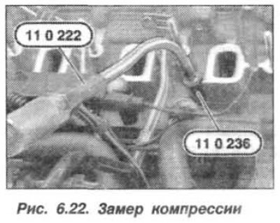
Measurement of the compression value allows you to identify the degree of wear of the valves, pistons, cylinder mirror, valve guides, and everything related to the gas distribution mechanism. Testing requires special equipment «11.2.236» (adapter) And «11.0.222» (compressometer), with pressure measurement limit up to 30 kgf/cm2.
The main measurement indicator of the compression gauge is the pressure value and its difference in values for individual cylinders for one engine. This difference should not be more than 1.5 kgf/cm2. If an excess of this value is detected, then the valves or their villages are damaged, the piston rings or cylinder liners are worn out. When the wear limit is reached, the engine must be removed and repaired or replaced.
To install the compression gauge, the glow plugs must be removed. The very value of the compression ratio also matters, for the engine «M57» it should be 20 - 22 kgf / cm2.
Checking the engine compression must be carried out with a fully charged battery, on a cold engine and in the following order.
Attention!
- Read out the fault memory of the DDE control unit and rectify faults if any are found.
- Set the gearshift lever to the neutral position.
- Disconnect the AL connecting the fuel injection injectors.
- The battery voltage and engine speed, during all measurements, must be the same.
- All air intake channels must be free.
Remove all glow plugs. Turn the engine shaft several times with the starter, which will remove the remaining waste products of combustion from it. Install fixture «11.0.236» into the glow plug socket (pic. 6.22). Connect fixtures «11.0.222» And «11.0.236».
Turn the engine shaft with a starter (8 - 10 turns) so that the increase in pressure across the device stops. Fix it in each engine cylinder.
In the future, install the devices sequentially in all the holes of the glow plugs and take measurements. Compare the results and draw conclusions.
Change gaskets, replace glow plugs (4) and tighten them to 18 Nm (1.8 kgf·m). Assemble and start the engine, read the information from the fault memory of the DDE control unit.
V-belt check
In the process of long-term operation, as well as with frequent use of the car in extreme conditions (off-road, puddles, mud, sand, deep snow) – Excessive wear of the V-belt profiles is possible.
Checking the V-belt must be carried out in the following order.
Remove the V-belt and measure the plain thickness (But) belt (pic. 6.23).
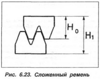
Measure folded value (H1) belt. The belt must be replaced if, depending on the value «But», received value «H1» less than below:
| – | But = 4.6 | H1 < 7.4 |
| – | But = 4.7 | H1 < 7.6 |
| – | But = 4.8 | H1 < 7.8 |
| – | But = 4.9 | H1 < 8.0 |
| – | But = 5.0 | H1 < 8.2 |
| – | But = 5.1 | H1 < 8.4 |
| – | But = 5.2 | H1 < 8.6 |
| – | But = 5.3 | H1 < 8.8 |
| – | But = 5.4 | H1 < 9.0 |
Replacing the alternator drive belt
Attention! When reusing the alternator drive belt, note the direction of its movement in order to install it in the same direction.
The tension roller is under spring pressure.
The alternator drive belt must be replaced in the following order. Remove soundproof cover and fan. Remove the A/C compressor drive belt.
Install the tool vertically on the tensioner hexagon so that its lever points upwards.
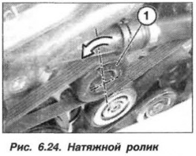
Release tension roller (1, fig. 6.24) alternator drive belt in a counterclockwise direction and remove the belt (2) generator drive.
Attention! Check the alternator drive belt for traces of coolant and oil, as well as mechanical damage. If present, replace the alternator belt.
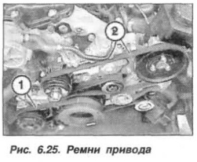
Install the removed drive belts on the pulleys and check their correct position (pic. 6.25). Assemble the engine.