
- Home
- BMW X5
- E53
- Diesel engine M57
- Power and exhaust system
- Fuel Supply System — General Information
Fuel Supply System — General Information (BMW X5 E53)
The basic diagram of the fuel supply system is shown in Figure 6.16 and is designed to supply such a quantity of fuel to the combustion chamber that ensures complete combustion of the fuel, a given power mode, the required level of exhaust toxicity and consists of the following elements:
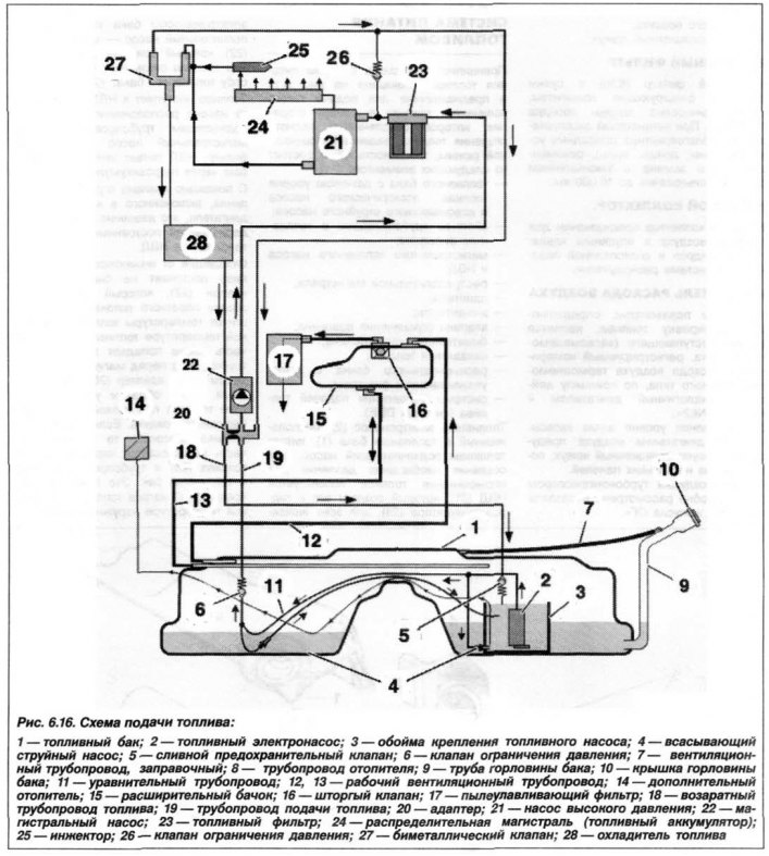
The fuel electric pump (2), located in the fuel tank (1), supplies fuel to the booster pump. To create the pressure required for fuel injection, the high-pressure fuel pump (21) is used, which creates it in the hydraulic accumulator (24), for all injectors (25). Between the high-pressure fuel pump and the fuel electric pump of the tank, an additional pump is installed - the main pump (22), which supports the fuel tank pump in case of high fuel consumption.
Fuel is supplied to the HPN from the fuel pump located in the tank via the supply lines, through the main pump and the fuel filter. The HPN supplies the injectors with fuel through the hydraulic accumulator.
With the help of a pressure limiting valve included in the engine supply circuit, this pumping pressure is maintained constant. The valve is installed on the high-pressure fuel pump.
The fuel leaving the injectors and the high-pressure fuel pump enters the bimetallic valve (27), which distributes the volume of the return flow depending on the fuel temperature. At low fuel temperatures, most of it again enters the supply line before the main pump through the adapter (20) with 5 outlets, thus accelerating the heating of the fuel at low outside air temperatures. If the fuel temperature is high, most of it returns through the fuel cooler (28) and the return line to the fuel tank. This prevents excessive heating of the fuel at high outside air temperatures.
The return flow of fuel can be large and hot under extreme operating conditions. For example, when driving uphill or with a trailer. Therefore, through the throttle located in the adapter, part of the fuel is diverted directly into the supply line. This measure additionally prevents excessive heating of the fuel in the tank.
Diesel fuel evaporates poorly, so there is no need for an adsorber. Fuel vapor condensate from the expansion tank (15) returns to the fuel tank. When refuelling, the tank is ventilated through the refuelling ventilation pipe (7) in the filler neck.
The fuel tank (1) is designed to store the required fuel supply while the vehicle is moving. The plastic fuel tank is two-section, saddle-type, located under the rear seat cushion and secured to the body with tension straps. Its capacity is 93 liters. The current fuel supply and its consumption are monitored by two level sensors, each in its own section, the information is displayed on an arrow-type device, the onset of the reserve (critical) the fuel volume is recorded by an indicator on the instrument panel. The tank is equipped with a ventilation system through an expansion tank and a filter.
Fuel pump (2) rotary, submersible type, with electric drive manufactured by Bosch (Germany) is installed in the right half of the fuel tank (if you look in the direction of movement).
To maintain the required fuel pressure in high-power modes, a main fuel pump is installed in the fuel system, which supplies an increased amount of fuel, exceeding its consumption by the engine. This pump is controlled by the electronic unit of the "EKR" system and is located in the luggage compartment on the right side. The control unit records the characteristics of the fuel demand, with the help of which the total amount of fuel required is calculated from the following values - the engine's fuel demand according to the requests of the ECU-DDE and the fuel required for lubrication and cooling of the high-pressure pump (HP).
The fuel filter is installed on the discharge pipeline after the main fuel pump. The filter housing contains a porous filter element with a retention capacity of 8–10 μm and a filter surface of about 7,500 cm². The fuel filter has a pressure sensor that switches on the main pump.
The engines are equipped with an electronic digital engine control system (DECS).
The TsSUD is designed to control all engine operating processes to ensure specified parameters of power, economy and toxicity of the vehicle. It is also responsible for controlling the automatic transmission, brake system elements - ABS, DSC, RDC, EDC, AGR and a number of other functions.
BMW vehicles are equipped with digital engine management systems of the type "DDE 4.0" on the M57 and of the type "DDE 5.06" on the M57TU – ("Digitale Diesel Elektronic").
The fuel injection control subsystem is an advanced electronic fuel injection system with a hot-wire type mass air flow meter.
The operating principle of the fuel injection control subsystem is as follows. The electric fuel pump (2) takes fuel from the tank and supplies it under pressure through the main pump (22) and the fuel filter (23) to the high-pressure fuel pump (21), then to the hydraulic accumulator (24), connected to each cylinder through the electromagnetic fuel injection valve - injector (25).
The fuel pressure regulator installed on the high-pressure fuel pump body maintains a constant injection pressure created in the hydraulic accumulator and drains excess fuel into the tank, i.e. it ensures fuel circulation in the system and prevents the formation of vapor locks in it. The fuel pump in the tank is switched on by the command of the ECU-DDE, which is triggered at an engine crankshaft speed of 30 min⁻¹, when the starter is turned on, after the starting plugs have warmed up. When the engine is not running, an emergency stop of fuel supply is provided if the engine stalls as a result of an accident or road traffic accident.
Each injector is controlled by a separate output stage of the ECU-KSUD amplification. This ensures the accuracy of the injected fuel dosage and its rapid adjustment when the engine load changes.
The hydraulic accumulator (24) is a cavity with sockets (holes) for installation of pressure pipelines of injectors, pressure sensor and pipe supply nipple from high-pressure fuel pump. The hydraulic accumulator provides fuel supply under the same pressure to the injectors. Its volume is specially calculated to reduce noise when changing operating modes and pressure drops.
Injectors (electromagnetic valve injectors) are designed for the metered supply of fuel injected into the engine combustion chamber. They are installed on the cylinder head. The amount of fuel injected depends on the open time of the injector, which is determined by the ECU-KSUD based on information received from the sensors.
Difficulty starting, failure to start, and unstable engine operation at idle indicate a possible injector malfunction. The crankshaft position sensor is mounted on the cylinder head, linked to the camshaft position, and is designed to determine the position of the pistons in the cylinders, which determines the moment and amount of fuel supplied at the same time. It is based on the Hall effect and generates a pulse of the first cylinder position at the top dead center (TDC) of the compression stroke, which is the reference signal for the start of the count. The crankshaft speed sensor is mounted on the cylinder block, above its flywheel, and is designed to determine the engine crankshaft speed to generate a control signal to open the injectors. It is based on the Hall effect and generates a pulse of one full crankshaft revolution, which is the reference signal for calculating the engine crankshaft speed and its instantaneous angular position.
The coolant temperature sensor is a resistor with a negative temperature coefficient, i.e. its resistance decreases as the temperature increases. During engine warm-up, the ECU-KSUD provides enrichment of the fuel mixture based on the electrical signal coming from the temperature sensor installed in the cylinder head.
The boost pressure sensor is designed to change the geometry of the turbocharger, which allows for optimal selection of boost pressure depending on the engine crankshaft speed. The sensor is supplied with a voltage of 5.0±0.25 V and has measurement limits of 50–240 kPa.
All elements of the engine fuel supply are connected to each other by fuel lines and hoses on nipple or clamp connections. If the engine does not start, starts with difficulty or stalls after starting, as well as with increased fuel consumption and increased content of toxic compounds in the exhaust gases, it is necessary to check the serviceability of the coolant temperature sensor.
Additional functions of the central control system include self-diagnostics, monitoring of the maximum permissible engine crankshaft speed, turning on the BMW X5 E53 fuel pump, monitoring the battery voltage, communication with other systems such as automatic transmission, ABS, ASC, RDC, ride height control, rain sensor, and airbags.
The self-diagnostic system detects malfunctions in the ECU-CSUD operation and enters them into memory as codes. If the coolant temperature sensors and air flow meter are faulty, the system switches to operation based on average values embedded in the engine control program. Reading codes at the service station allows you to quickly identify the cause of the malfunction and eliminate it.
As soon as the engine shaft speed reaches its maximum value, the fuel supply to the engine cylinders is interrupted by switching off the injectors on command from the ECU-CSUD.
And although the evaporation rate of diesel fuel is very low, the design provides for an expansion tank (15) of fuel vapors, which is designed to condense diesel fuel vapors by expanding them and returning diesel fuel to its tank. The expansion tank is connected to the atmosphere through a dust-catching filter (17).
The original article is available on the website: «bmwman.ru»
- fuel tank with fuel level sensor, electric pump and suction jet pump;
- fuel filter piping systems;
- main fuel pump and high pressure pump (HP);
- distribution main;
- adapter;
- injectors;
- pressure relief valves;
- bimetallic valve;
- fuel cooler;
- expansion tank with dust filter;
- fuel management systems (dDE system).
The fuel electric pump (2), located in the fuel tank (1), supplies fuel to the booster pump. To create the pressure required for fuel injection, the high-pressure fuel pump (21) is used, which creates it in the hydraulic accumulator (24), for all injectors (25). Between the high-pressure fuel pump and the fuel electric pump of the tank, an additional pump is installed - the main pump (22), which supports the fuel tank pump in case of high fuel consumption.
Fuel is supplied to the HPN from the fuel pump located in the tank via the supply lines, through the main pump and the fuel filter. The HPN supplies the injectors with fuel through the hydraulic accumulator.
With the help of a pressure limiting valve included in the engine supply circuit, this pumping pressure is maintained constant. The valve is installed on the high-pressure fuel pump.
The fuel leaving the injectors and the high-pressure fuel pump enters the bimetallic valve (27), which distributes the volume of the return flow depending on the fuel temperature. At low fuel temperatures, most of it again enters the supply line before the main pump through the adapter (20) with 5 outlets, thus accelerating the heating of the fuel at low outside air temperatures. If the fuel temperature is high, most of it returns through the fuel cooler (28) and the return line to the fuel tank. This prevents excessive heating of the fuel at high outside air temperatures.
The return flow of fuel can be large and hot under extreme operating conditions. For example, when driving uphill or with a trailer. Therefore, through the throttle located in the adapter, part of the fuel is diverted directly into the supply line. This measure additionally prevents excessive heating of the fuel in the tank.
Diesel fuel evaporates poorly, so there is no need for an adsorber. Fuel vapor condensate from the expansion tank (15) returns to the fuel tank. When refuelling, the tank is ventilated through the refuelling ventilation pipe (7) in the filler neck.
Fuel tank
The fuel tank (1) is designed to store the required fuel supply while the vehicle is moving. The plastic fuel tank is two-section, saddle-type, located under the rear seat cushion and secured to the body with tension straps. Its capacity is 93 liters. The current fuel supply and its consumption are monitored by two level sensors, each in its own section, the information is displayed on an arrow-type device, the onset of the reserve (critical) the fuel volume is recorded by an indicator on the instrument panel. The tank is equipped with a ventilation system through an expansion tank and a filter.
Fuel pump and filter
Fuel pump (2) rotary, submersible type, with electric drive manufactured by Bosch (Germany) is installed in the right half of the fuel tank (if you look in the direction of movement).
To maintain the required fuel pressure in high-power modes, a main fuel pump is installed in the fuel system, which supplies an increased amount of fuel, exceeding its consumption by the engine. This pump is controlled by the electronic unit of the "EKR" system and is located in the luggage compartment on the right side. The control unit records the characteristics of the fuel demand, with the help of which the total amount of fuel required is calculated from the following values - the engine's fuel demand according to the requests of the ECU-DDE and the fuel required for lubrication and cooling of the high-pressure pump (HP).
The fuel filter is installed on the discharge pipeline after the main fuel pump. The filter housing contains a porous filter element with a retention capacity of 8–10 μm and a filter surface of about 7,500 cm². The fuel filter has a pressure sensor that switches on the main pump.
Fuel injection system
The engines are equipped with an electronic digital engine control system (DECS).
Attention!
- Disconnecting the wires from the battery terminals is permitted only when this is provided for by the work procedure. When disconnecting the battery, the fault codes, audio equipment settings and anti-theft system locks entered into the ECU-KSUD memory device are erased.
- Disconnection of plug connections (PC) should be carried out only with the ignition off.
- If the injection system malfunctions, before you begin to determine the faults in the ECU-CSUD or other control element, check the condition of the injection system.
The TsSUD is designed to control all engine operating processes to ensure specified parameters of power, economy and toxicity of the vehicle. It is also responsible for controlling the automatic transmission, brake system elements - ABS, DSC, RDC, EDC, AGR and a number of other functions.
BMW vehicles are equipped with digital engine management systems of the type "DDE 4.0" on the M57 and of the type "DDE 5.06" on the M57TU – ("Digitale Diesel Elektronic").
Fuel injection control subsystem
The fuel injection control subsystem is an advanced electronic fuel injection system with a hot-wire type mass air flow meter.
The operating principle of the fuel injection control subsystem is as follows. The electric fuel pump (2) takes fuel from the tank and supplies it under pressure through the main pump (22) and the fuel filter (23) to the high-pressure fuel pump (21), then to the hydraulic accumulator (24), connected to each cylinder through the electromagnetic fuel injection valve - injector (25).
The fuel pressure regulator installed on the high-pressure fuel pump body maintains a constant injection pressure created in the hydraulic accumulator and drains excess fuel into the tank, i.e. it ensures fuel circulation in the system and prevents the formation of vapor locks in it. The fuel pump in the tank is switched on by the command of the ECU-DDE, which is triggered at an engine crankshaft speed of 30 min⁻¹, when the starter is turned on, after the starting plugs have warmed up. When the engine is not running, an emergency stop of fuel supply is provided if the engine stalls as a result of an accident or road traffic accident.
Each injector is controlled by a separate output stage of the ECU-KSUD amplification. This ensures the accuracy of the injected fuel dosage and its rapid adjustment when the engine load changes.
The hydraulic accumulator (24) is a cavity with sockets (holes) for installation of pressure pipelines of injectors, pressure sensor and pipe supply nipple from high-pressure fuel pump. The hydraulic accumulator provides fuel supply under the same pressure to the injectors. Its volume is specially calculated to reduce noise when changing operating modes and pressure drops.
Injectors (electromagnetic valve injectors) are designed for the metered supply of fuel injected into the engine combustion chamber. They are installed on the cylinder head. The amount of fuel injected depends on the open time of the injector, which is determined by the ECU-KSUD based on information received from the sensors.
Difficulty starting, failure to start, and unstable engine operation at idle indicate a possible injector malfunction. The crankshaft position sensor is mounted on the cylinder head, linked to the camshaft position, and is designed to determine the position of the pistons in the cylinders, which determines the moment and amount of fuel supplied at the same time. It is based on the Hall effect and generates a pulse of the first cylinder position at the top dead center (TDC) of the compression stroke, which is the reference signal for the start of the count. The crankshaft speed sensor is mounted on the cylinder block, above its flywheel, and is designed to determine the engine crankshaft speed to generate a control signal to open the injectors. It is based on the Hall effect and generates a pulse of one full crankshaft revolution, which is the reference signal for calculating the engine crankshaft speed and its instantaneous angular position.
The coolant temperature sensor is a resistor with a negative temperature coefficient, i.e. its resistance decreases as the temperature increases. During engine warm-up, the ECU-KSUD provides enrichment of the fuel mixture based on the electrical signal coming from the temperature sensor installed in the cylinder head.
The boost pressure sensor is designed to change the geometry of the turbocharger, which allows for optimal selection of boost pressure depending on the engine crankshaft speed. The sensor is supplied with a voltage of 5.0±0.25 V and has measurement limits of 50–240 kPa.
All elements of the engine fuel supply are connected to each other by fuel lines and hoses on nipple or clamp connections. If the engine does not start, starts with difficulty or stalls after starting, as well as with increased fuel consumption and increased content of toxic compounds in the exhaust gases, it is necessary to check the serviceability of the coolant temperature sensor.
Additional functions of the central control system include self-diagnostics, monitoring of the maximum permissible engine crankshaft speed, turning on the BMW X5 E53 fuel pump, monitoring the battery voltage, communication with other systems such as automatic transmission, ABS, ASC, RDC, ride height control, rain sensor, and airbags.
The self-diagnostic system detects malfunctions in the ECU-CSUD operation and enters them into memory as codes. If the coolant temperature sensors and air flow meter are faulty, the system switches to operation based on average values embedded in the engine control program. Reading codes at the service station allows you to quickly identify the cause of the malfunction and eliminate it.
As soon as the engine shaft speed reaches its maximum value, the fuel supply to the engine cylinders is interrupted by switching off the injectors on command from the ECU-CSUD.
Fuel tank expansion tank
And although the evaporation rate of diesel fuel is very low, the design provides for an expansion tank (15) of fuel vapors, which is designed to condense diesel fuel vapors by expanding them and returning diesel fuel to its tank. The expansion tank is connected to the atmosphere through a dust-catching filter (17).
The original article is available on the website: «bmwman.ru»
This article is available at russian, bulgarian, belarusian, ukrainian, serbian, croatian, romanian, polish, slovak, hungarian
Article verified: Zhuravleva Isolda
Share information:
Previous articles
БМВ E53: Power and exhaust system
Next articles
Similar articles on other types of BMW cars:
Engine power supply system. General information BMW 3 Series E30 (1982-1994)
Engine power supply system. General information BMW 3 Series E36 (1990-2000)
Engine power supply system — general information and design BMW 5 Series E34 (1988-1996)
Power supply system — general information BMW 5 Series E39 (1995-2003)
Fuel system. General description BMW 7 Series E32 (1986-1994)
General information about security system elements BMW 7 Series E38 (1994-2001)
Tachometer — general information BMW X3 E83 (2003-2010)
Link in different formats to this page
Visitor comments
No comments yet
- General information
- Manual
- Maintenance
- M54 petrol engine
- Engine repair
- Lubrication system
- Cooling system
- Supply system
- Injection system
- Exhaust system
- Engine electrics
- M62 petrol engine
- Engine repair
- Lubrication system
- Cooling system
- Supply system
- Exhaust system
- Engine electrics
- N62 petrol engine
- Engine repair
- Cooling and lubrication system
- Power and exhaust system
- Engine electrics
- Diesel engine M57
- Engine repair
- Lubrication system
- Cooling system
- Power and exhaust system
- Engine electrics
- Turbocharging system
- Transmission
- Clutch
- Mechanical gearbox
- Automatic gearbox
- Transfer case and cardan
- Chassis
- Brake system
- Steering
- Front suspension
- Rear suspension
- Wheels and tires
- Body
- Exterior
- Interior
- Doors and windows
- Repair and maintenance
- Heater and air conditioner
- Electrical equipment
- Equipment and devices
- Levers and switches
- Electrical circuits