
Attention!
- Ensure adequate exhaust ventilation and cleanliness of the workplace.
- Prevent damage to seals.
- The fuel hoses are under pressure.
- Do not allow the sensor bracket to bend.
The fuel level indicator sensor on the right side of the fuel tank must be removed in the following order. Prepare the "16.1.020" device, a container for collecting leaking fuel and a clean rag. Turn off the engine and let it cool down. Completely pump out the fuel from the fuel tank. Remove the rear seat and fold the trim panel forward.
Separate the insulating mat along the perforation and fold it back, while removing the rubber plug and fold back the rubber mat.
Note: When performing operations, do not damage the seals and take into account that the fuel hoses are under pressure.
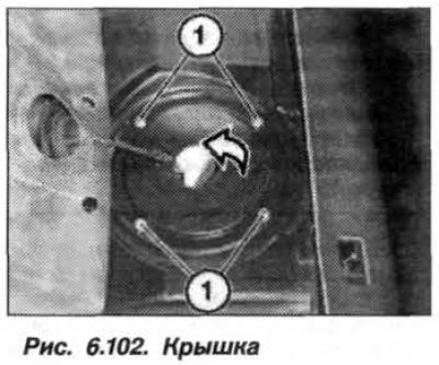
Remove the screws (1, Fig. 6.102) on the left and right sides. Fold back the metal covers of the left and right fuel level sensor units. Unlock and disconnect the supply and return pipes. Unlock and disconnect IIIC from the right fuel level sensor unit. If necessary, unlock and disconnect the hose of the autonomous heating system.
Rotate the hose to the right and left, slightly moving it from its place together with the clamp. Loosen the hose clamp, carefully disconnect the hose. In doing so, avoid damaging the connecting nipple.
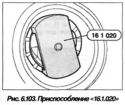
Using the device "16.1.020" (fig. 6.103), unscrew the threaded caps of the left and right sensor units.
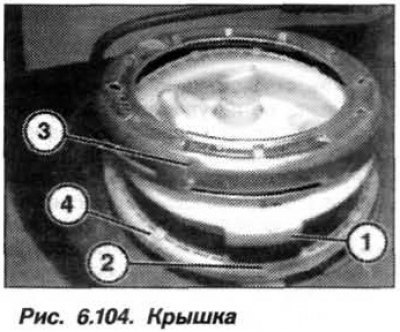
Carefully lift the connection cover (1, Fig. 6.104). Do not pull too hard on the fuel supply hose connector. Pay attention to the leaking fuel, which must be collected in a container and sent for disposal.
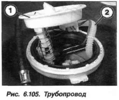
Carefully remove the sensor assembly from the fuel tank. Unlock and disconnect the pipe (1, Fig. 6.105).
Press the latch down and remove the suction jet pump from the holder. Press the latch and disconnect the hose bundle connector. Carefully remove the right sensor assembly from the fuel tank.
Caution! The fuel pump mounting collar is filled with fuel.
Pour the fuel through the top hole into the container and remove the hose bundle from the fuel tank.
The installation of the fuel level indicator sensor on the right side of the fuel tank should be carried out in the reverse order, while it is necessary.
Replace the rubber seal of the fill level sensor and screw the rubber seal onto the edges of the sensor. Before pressing the sensor, detach the rubber seal from the edges and insert it into the hole of the fuel tank.
Insert the sensor flange horizontally into the hole in the fuel tank so that the base of the sensor fits vertically into the recess in the bottom of the fuel tank. Make sure that the lug (1, see Fig. 6.104) on the sensor, entered the sample (2) on the tank.
When tightening the threaded plug to a torque of 45 N·m (4.5 kgf·m), the tooth (4) on the tank enters the groove (3) on the plug with an audible click and the feeling of the fixing moment;
Replace the hose clamps and tighten their screws to a torque of 2.0 N·m (0.2 kgf·m) for a diameter of 10–16 mm.
The new sensor unit comes with a plastic shield over the hose bundle. Hook the tab of the plastic shield with a suitably curved wire and use it to pull the shield out of the fuel tank without damaging its coating. Remove the plastic shield after filling the hose bundle.
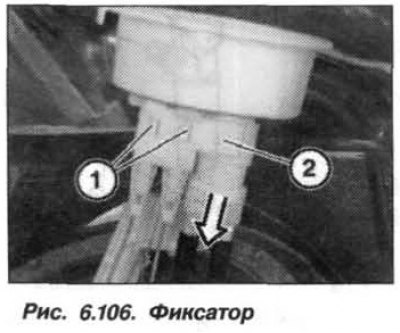
When replacing the left fuel level sensor, it is necessary to release the clamps (1, Fig. 6.106) and remove the level sensor from the mounting unit. Unlock the SS and remove it from the mounting unit.