
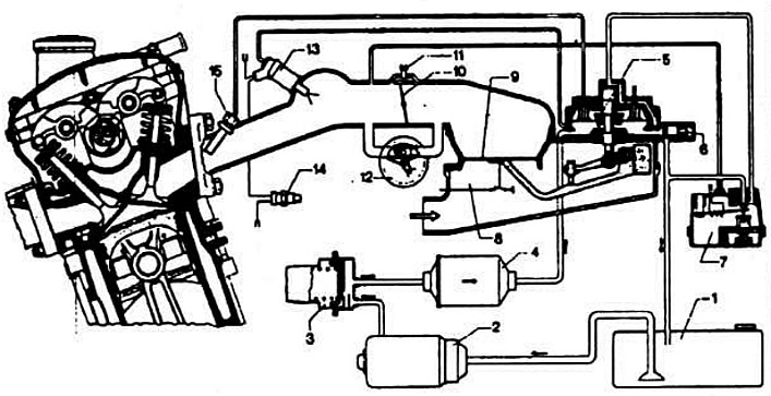
Scheme of fuel injection system "K-Jetronic":
1 - fuel tank; 2 - fuel pump; 3 — fuel storage tank; 4 - fuel filter; 5 — fuel dispenser; 6 - supply pressure regulator; 7 — control pressure regulator; 8 - air flow meter; 9 — air flow meter pressure disk; 10 — throttle valve; 11 — idle mixture quantity adjusting screw; 12 — additional air supply valve; 13 - starting nozzle; 14 - thermal time relay; 15 — injection nozzles.
The K-Jetronic fuel injection system is a mechanical system of constant fuel injection. The injectors constantly spray fuel in the intake manifold before the intake valves. Therefore, the change in fuel consumption is achieved not by changing the duration of the injector opening, but by regulating the amount of fuel supplied to the injectors.
The amount of air supplied is continuously measured by the air flow meter, and the amount of fuel injected is strictly proportional to the amount of air supplied (with the exception of a number of engine operating modes such as starting a cold engine, operating under full load, etc.) and is regulated by a fuel dispenser-distributor.