
Table of contents: Adjusting the throttle position ↓ Adjusting engine idle speed ↓ Checking the fuel dispenser ↓ Checking the starting injector ↓ Checking the thermal time relay ↓ Checking the performance of the fuel…↓ Pressure check ↓ Checking the control pressure on a…↓ Checking the control pressure on a…↓ Checking fuel supply pressure on a…↓ Checking the condition of the…↓ Checking the additional fuel supply…↓ Possible malfunctions of the fuel…↓
- Home
- BMW 3 Series
- E21
- 4-cylinder engine
- Supply system
- Fuel injection system
Fuel injection system (BMW 3 Series E21)
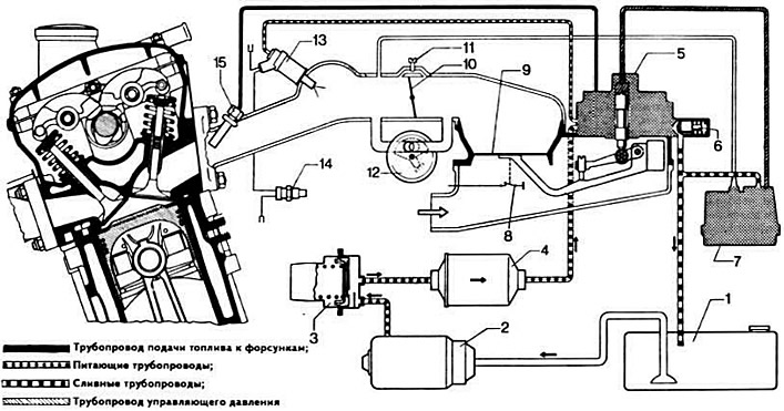
Scheme of fuel injection system "K-Jetronic":
1 - fuel tank; 2 - fuel pump; 3 — fuel storage tank; 4 - fuel filter; 5 — fuel dispenser; 6 - supply pressure regulator; 7 — control pressure regulator; 8 - safety switch; 9 — air flow meter pressure disk; 10 — throttle valve; 11 — idle speed adjusting screw; 12 — additional air supply valve; 13 - starting nozzle; 14 - thermal time relay; 15 — injectors.
The design features and operation of the K-Jetronic fuel injection system from Bosch are described in the subsection "Fuel injection system" of the section "Six-cylinder engine".
Adjusting the throttle position
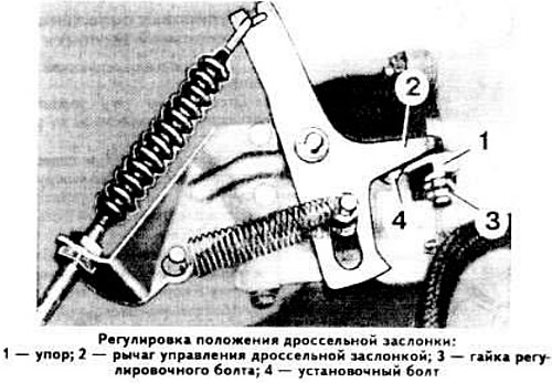
Disconnect the throttle control rod from the lever.
Loosen nut 3 and tighten bolt so that the gap between stop 1 and throttle control lever 2 becomes equal to 1±0.5 mm.
Loosen the mounting bolt 4 and move the throttle valve in the housing so that there is no gap between the throttle valve and the housing wall.
Tighten the installation bolt 4, then tighten bolt 3 by 1 turn; the throttle valve should move without sticking and should not touch the housing walls. Tighten nut 3.
Connect the throttle control rod to the lever and adjust the throttle control rod if necessary.
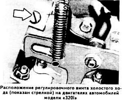
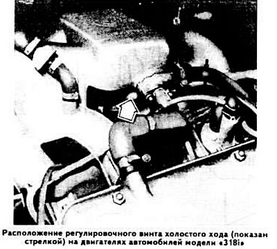
Adjusting engine idle speed
Warm up the engine.
Use the adjusting screw to set the crankshaft speed within 900±50 rpm.
Check the carbon monoxide (CO) content in the exhaust gases, which should correspond to the value specified in subsection "Detailed technical specifications".
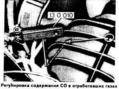
If necessary, remove (using mandrel 131012 for "3181") the plug of the mixture quality (composition) adjusting screw and using a special mandrel (130010 for "320i" or 130020 for "318i") achieve the proper CO content in the exhaust gases.
Do not increase engine speed during adjustment.
After completing the adjustment, install a new plug in the hole for the mixture quality adjusting screw (using the 131013 drift for the "318i").
Checking the fuel dispenser
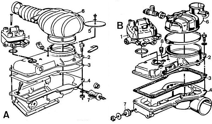
Fuel distributor-distributor of the fuel injection system of engines of cars of the models: A — "320i"; B — "318i":
1 — fuel dispenser; 2 - air flow meter; 3 - gasket; 4 — lower housing of the mixture regulator; 5 — air flow meter pressure disk; 6 — air supply casing; 7 — silent blocks; 8 — plug for adjusting screw of mixture quality (composition).
Remove the plastic air supply cover.
Activate the fuel pump by turning on the ignition for a few seconds and simultaneously lifting the air flow meter pressure disk manually or with a magnet. In this case, uniform resistance should be felt throughout the entire stroke of the pressure disk. Moving the pressure disk downwards should not require effort.
When the pressure disk touches the walls of the air flow meter housing, unscrew the central screw securing the pressure disk and center it by placing a 10 mm thick gasket at four points around the circumference.
Ensure that the pressure disc is level with or no more than 0.5 mm below the start of the expanding cone of the air flow meter body.
If necessary, adjust the position of the air flow meter pressure disk by bending the spring clip, after removing the lower housing of the mixture regulator.
Checking the starting injector
Disconnect the thermal time relay plug and connect the brown wire with the black stripe (terminal "W") to ground.
Disconnect the wire from terminal "50" of the starter solenoid relay.
Remove the starting injector from the intake manifold.
Connect terminal "30" of the starting relay to the "+" terminal of the battery.
In this case, the starting nozzle sprayer should spray fuel.
If the pilot injector needle does not open or if fuel drips from the injector nozzle after the needle closes, replace the pilot injector.
Checking the thermal time relay
Disconnect the thermal time relay plug.
Connect the test lamp with one wire to the "+" terminal of the battery and the other to the "W" plug of the thermal time relay.
If the coolant temperature is above plus 15°C, the indicator lamp should not light, and if the coolant temperature is below plus 15°C, it should light.
Checking the performance of the fuel pump
Disconnect the fuel drain hose from the fuel dispenser.
Attach a hose to the fuel drain fitting of the fuel dispenser and place a measuring cup under its free end.
Activate the fuel pump and check its performance, which should be equal to 750 cm³ of fuel in 30 s.
Pressure check
Connect one hose of the pressure gauge with a two-way valve 133060 to the control pressure fitting of the fuel dispenser-distributor, and the other to the control pressure line.
Disconnect the plug connectors of the control pressure regulator and the additional air supply valve.
Checking the control pressure on a cold engine
The control pressure on a cold engine should only be checked if the cold engine has difficulty starting or if the engine runs poorly during warm-up.
Disconnect the mixture regulator plug.
Turn on the ignition and open the two-way valve of the pressure gauge
Take the pressure gauge readings and compare the obtained value depending on the coolant temperature with the graph provided on page (see section "Six-cylinder engine").
If the measured pressure is below normal, the control pressure regulator is faulty.
If the measured pressure is higher than normal, this indicates insufficient fuel drainage or a malfunction of the control pressure regulator. Check the condition of the drain pipe, install a new control pressure regulator and check its performance.
Checking the control pressure on a hot engine
Connect the plug connector of the control pressure regulator.
Turn on the ignition, having first opened the two-way valve of the pressure gauge and disconnected the plug connector of the mixture regulator.
After 3 minutes from stopping the engine, the control pressure should be within 2.7-3.1 kg/cm².
Connect the plug connectors of the additional air supply valve and the mixture regulator.
Start the engine.
At idle, measure the control pressure, which should be within 3.4-3.8 kg/cm².
If the measurement result is below normal, check the condition of the additional air supply valve plug and the serviceability of the control pressure regulator.
If the measurement result is higher than normal, this indicates a defective vacuum hose, insufficient fuel drainage, or a malfunction of the control pressure regulator.
Checking fuel supply pressure on a cold or hot engine
With the engine stopped, close the two-way valve of the pressure gauge.
Disconnect the mixture regulator plug.
Turn on the ignition and measure the fuel supply pressure, which should be within 4.5-5.2 kg/cm².
Reasons for insufficient fuel supply pressure may be:
- leaks in fuel lines and their connections;
- contamination of the fine fuel filter;
- insufficient fuel supply from the fuel pump;
- violation of fuel supply pressure regulation.
The reasons for increased fuel supply pressure are:
- insufficient fuel drainage;
- violation of the adjustment of the fuel pressure regulator in the system or jamming of its plunger.
The fuel supply pressure is regulated by selecting the thickness of the adjusting washers installed on the plunger of the fuel pressure regulator in the system.
| Thickness of adjusting washers, mm | Change in fuel supply pressure, kg/cm² |
| 0,1 | 0,06 |
| 0,5 | 9,3 |
Checking the tightness of the system with the engine stopped
Open the two-way valve of the pressure gauge.
Turn on the ignition.
First disconnect and then connect the mixture regulator plug.
Turn off the ignition.
After a few minutes, the pressure in the system should be at least 1.7 kg/cm².
The reasons for the pressure in the system dropping below 1.7 kg/cm² may be: leaks in the pipelines and their connections, the check valve of the fuel pump or fuel storage tank.
Checking the condition of the injection nozzles
Unscrew the injectors from their sockets.
Lift the air flow meter pressure disc manually or with a magnet when there is residual pressure in the system.
Make sure that no more than one drop of fuel flows from the injector nozzles within 15 seconds.
Checking the additional fuel supply valve
Disconnect the control pressure regulator plug.
Disconnect the hoses from the additional air supply valve fittings.
When the coolant temperature is about plus 20°C, make sure that the passage hole is half open.
Connect the hoses to the additional air supply valve.
Connect the plug connector of the control pressure regulator.
Turn on the ignition and start the engine.
After 5 minutes of engine operation, the passage hole should be completely blocked.
Otherwise, replace the additional air supply valve.
Possible malfunctions of the fuel system and methods for their elimination
See section "Six-cylinder engine".
This article is available at russian, bulgarian, belarusian, ukrainian, serbian, croatian, romanian, polish, slovak, hungarian
Article verified: Polikarpov Saveliy
Share information:
Previous articles
БМВ E21: Supply system
Next articles
Similar articles on other types of BMW cars:
Fuel injection system parts «Kugelfischer» BMW 5 Series E12 (1972-1981)
Diagnostics of faults of fuel injection system of diesel engine BMW 5 Series E34 (1988-1996)
Diagnostics of diesel fuel injection system faults BMW 7 Series E32 (1986-1994)
Fuel and exhaust system specifications BMW 7 Series E38 (1994-2001)
Fuel injection system injectors (N47) BMW X3 E83 (2003-2010)
Fuel injection system defect BMW X5 E53 (1999-2006)
Link in different formats to this page
Visitor comments
No comments yet
- General information
- Manual
- Maintenance
- Power unit
- Engine repair
- Cooling system
- Power system (gasoline)
- Injection system (gasoline)
- Fuel system (diesel)
- Exhaust system
- Ignition system
- Charge and launch systems
- Transmission
- Car gearbox
- Clutch and drive shafts
- Chassis
- Brake system
- Suspension front and rear
- Steering
- Body
- Body care and repair
- Exterior
- Interior
- Electrical equipment
- Troubleshooting
- Lighting and signaling
- Equipment and devices
- Heater and air conditioner
- Electrical circuits
- General information
- Manual
- Repair on the road
- Weekly checks
- Maintenance
- Troubleshooting
- Power unit
- 4 cylinder engines
- 6 cylinder engines
- Engine overhaul
- Cooling and heating
- Fuel and exhaust system
- Starting and charging system
- Ignition system
- Transmission
- Clutch
- Mechanical gearbox
- Automatic gearbox
- Cardan and drive shafts
- Chassis
- Brake system
- Wheel suspension
- Steering
- Body
- Exterior
- Interior
- Electrical equipment
- Equipment and devices
- Electrical circuits
- General information
- Maintenance
- Power unit
- Engine repair
- Cooling system
- Ignition system
- Supply system
- Fuel injection system
- Exhaust system
- Transmission
- Clutch
- Car gearbox
- Front and rear axle
- Chassis
- Steering
- Brake system
- Body
- Exterior
- Interior
- Electrical equipment
- Heating system
- Equipment and devices
- Power devices
- Electrical circuits
- Power unit
- M10/M20 engine
- M40 engine
- Ignition system
- Lubrication system
- Cooling system
- Supply system
- Fuel injection
- Exhaust system
- Transmission
- Clutch
- Manual gearbox
- Front axle
- Rear axle
- Chassis
- Steering
- Brake system
- Body
- Exterior
- Interior
- Electrical equipment
- Heating system
- Equipment and devices
- Electrical circuits
- General information
- Specifications
- Operation and maintenance
- 4-cylinder engine
- Engine repair
- Cooling and lubrication system
- Supply system
- Ignition system
- 6-cylinder engine
- Engine repair
- Cooling and lubrication system
- Supply system
- Fuel injection system
- Ignition system
- Transmission
- Clutch
- 4-speed manual gearbox
- 5-speed manual gearbox
- Automatic gearbox
- Cardan and rear axle
- Chassis
- Steering
- Front suspension
- Rear suspension
- Brake system
- Electrical equipment
- Equipment and devices
- Electrical circuits