
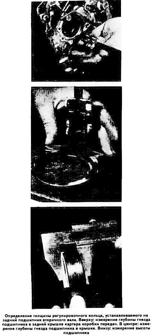
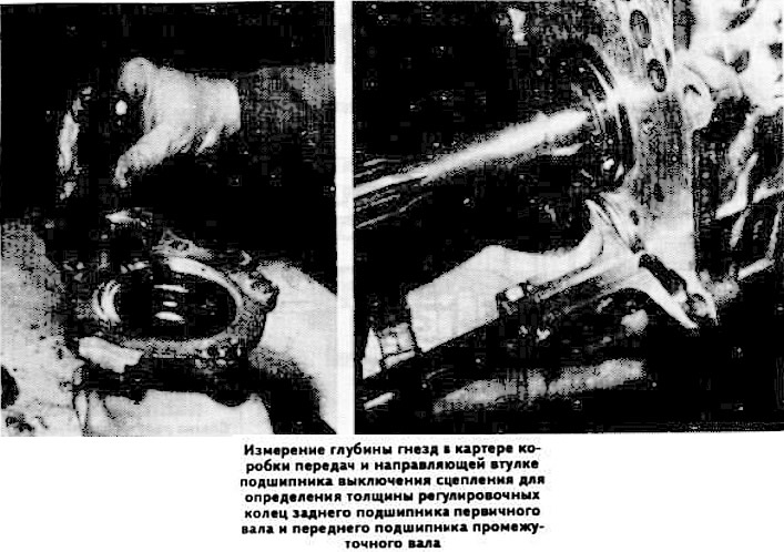
Add the measurements together and subtract the sum from the height of the secondary shaft rear bearing to determine the thickness of the adjusting ring to be installed.
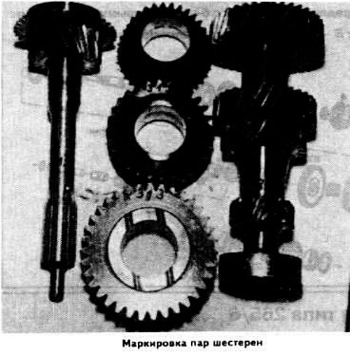
Warning: The gears are matched in pairs, so if one of them is damaged, that pair of gears must be replaced.
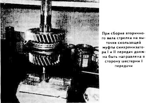
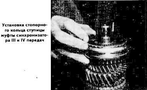
Install the parts on the secondary shaft in the following order: 2nd gear pinion, bearing, synchronizer locking ring, 1st and 2nd gear synchronizer sliding sleeve (with an annular groove towards the 1st gear), synchronizer locking ring (heating it up and pressing it until it stops), 1st gear pinion, 1st gear pinion needle bearing, reverse gear pinion (directing the wide lubricated surface towards the 1st gear pinion), bearing bushing and adjusting shims (using a 38x45 mm mandrel), adjusting ring, speedometer drive pinion (heating it up and pressing it in until it stops), bearing of the 3rd gear pinion, 3rd gear pinion with synchronizer locking ring, hub of the sliding clutch of the synchronizer of 3rd and 5th gears, retuning ring and with axe ring (ensuring their gap-free installation), bearing of the fourth gear pinion, fourth gear pinion and primary shaft with synchronizer locking ring.
Install a headless bolt to center the gear clusters.
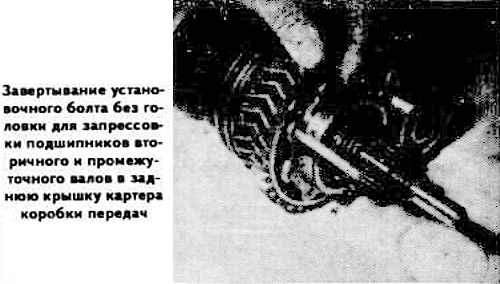
Heat the inner cavity of the rear cover to a temperature of 80-100°C to facilitate pressing in the rear bearings of the secondary and intermediate shafts.
Warning: When heating, direct the torch flame so that it does not touch the plastic driven gear of the speedometer drive.
Install the secondary shaft flange with a locking adhesive such as Loctite, lubricate the thread of its mounting nut with the same adhesive and tighten it to a torque of 11 kgf·m.
Install the rod and fork for shifting 1st and 2nd gears.
Install the reverse gear fork and rod, put the spring and the locking ball in place.
Install the locking balls of the 1st and 2nd gear and reverse gear locks, then insert the rod.
Insert the pin into the 1st and 2nd gear shift fork.
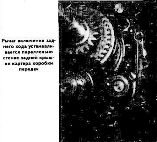
Position the reverse gear lever parallel to the gearbox housing and move the lever into the recess until it stops.
Install the III and IV gear shift fork and the gear selection rod. Move the lever and move the III and IV gear shift fork rod further forward.
Insert the detent balls and lock balls and push the gear selector rods all the way in, with the hole at the end of the gear selector rod in the vertical position.
Insert the locking pins into the shift fork shafts, insert the longest pin into the gear selector shaft.
Install the stem plugs.
Tighten the secondary shaft rear bearing cover hexagon socket head cap bolts.
Connect the gearbox housing to the rear cover and tighten the mounting bolts.
Press the front bearing of the intermediate shaft into the crankcase socket first, then the rear bearing of the primary shaft with an adjusting washer of the same size until it stops against the retaining ring.
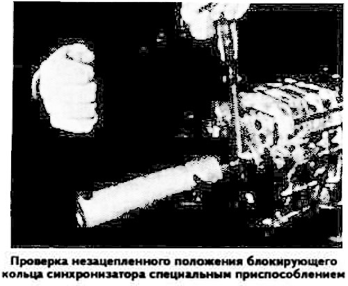
Using a special device, check that the locking ring of the 4th gear synchronizer (see photo) is in the unengaged state.
Install the adjusting ring and the primary shaft rear bearing mounting ring.
Determine the thickness of the adjusting rings of the rear bearing of the primary shaft and the front bearing of the intermediate shaft as the difference between the protrusion of the bearings relative to the plane of the gearbox housing and the depth of the bearing seat in the front cover of the housing.
Install the front gearbox housing cover and adjusting rings of the thickness determined in the manner specified. Note that the three upper front cover mounting bolts are longer than the others.