
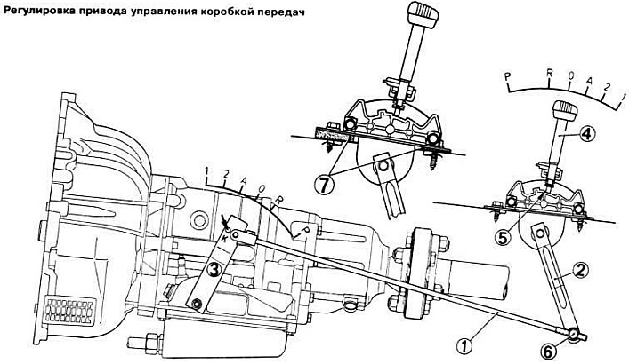
Make sure the transaxle cross member is securely fastened.
Disconnect draft 1 of a drive of management of a transmission from the intermediate lever 2 of a choice of transfers.
Set the gear selection lever 3 on the gearbox housing to position «0» (or «N»).
Move the selector lever 4 until it stops against the backstage stop 5.
Change the length of the link 1 of the gearbox control drive so that the hinge 6 coincides with the lower part of the intermediate lever 2 of the gear selection.
Reduce the length of the transmission control link 1 by turning its end one full turn.
Attach draft 1 of a drive of management of a transmission to the intermediate lever 2 of a choice of transfers.
Throttle linkage adjustment on vehicles with 4-cylinder engines
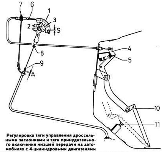
Warm up the engine.
Make sure that:
- throttle control sector 1 rests on stop 2;
- the lever 4 of the accelerator pedal 10 rests on the stop 5.
By turning nuts 7, adjust the length of the throttle control rod so that it is not overtightened.
At the same time, the gap «S» in the threaded connection of the throttle control sector should be within 0.2-0.3 mm.
Check whether the throttle valve opening limiter 3 rests against stop 2 when the accelerator pedal is in full throttle position.
Adjustment of draft of forced inclusion of the bottom transfer on cars with 4-cylinder engines
Adjust the throttle control rod.
With the accelerator pedal position corresponding to idling, adjust the gap with screw 8 "A", which should be in the range of 0.25-0.50 mm.
Press the accelerator pedal to the forced low gear position and measure the gap ''A'', which should be between 43.5-51.5 mm.
If the obtained value does not fit within the specified limits, achieve the proper clearance by turning the screw 11.
Adjusting the Throttle Control Rod and Low Gear Control Rod on Vehicles with O-Cylinder Engines
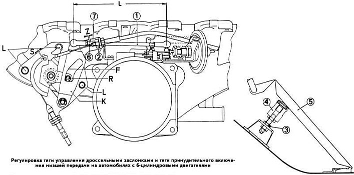
Check length «L» thrust 1, which should be within 165±0.5 mm. In case of deviation from the norm, achieve the proper size by turning the nuts on the ends of the rod.
Make sure the roller «R» throttle linkage lever rests on the work surface «F» slotted lever «TO» and that its idling before the travel of the throttle control sector does not exceed 1.5 mm. If necessary, achieve this condition by moving the throttle control actuator in the oval holes «L», shown on the left side of the figure.
With the accelerator pedal released, the throttle control rod must not be tensioned. At the same time, the gap «D» in the threaded connection of the throttle control sector should be 0.5 mm.
Check the clearance while the engine is idling «Z» between the tip 6 of the throttle control rod and the end of the rod 7, which should be within 0.25-0.75 mm. If necessary, achieve the correct size with nuts 2.
After loosening the nut 3 under the accelerator pedal, screw in stop 4 for forced downshifting.
Depress the accelerator pedal to full throttle position. Without changing the position of the accelerator pedal, unscrew the stop 4 for forced engagement of the lower gear until it comes into contact with the accelerator part.
Press the accelerator pedal sharply to the stop, i.e. to the forced downshift position. At the same time, the gap «Z» between the tip 6 and the end of the rod 7 must be at least 45 mm.