
Table of contents: Removal ↓ Installation ↓
- Home
- BMW 3 Series
- E46
- Chassis
- Suspension front and rear
- Removal and installation the front suspension beam
Removal and installation the front suspension beam (BMW 3 Series E46)
After installation, the front suspension beam must undergo geometric testing.
Removal
1. Remove the lower engine compartment cover, refer to Section Removal and installation the lower engine compartment cover.
2. Raise the engine and unscrew the engine mount fasteners from the beam on the left and right, refer to Section Removal and installation the oil pan.
3. Mark the position of the corresponding front wheel relative to the hub with paint. This will allow the balanced wheel to be installed in its original position during assembly. Loosen the wheel mounting bolts with the car on the ground. Raise the front of the car, place it on stands and remove the front wheel.
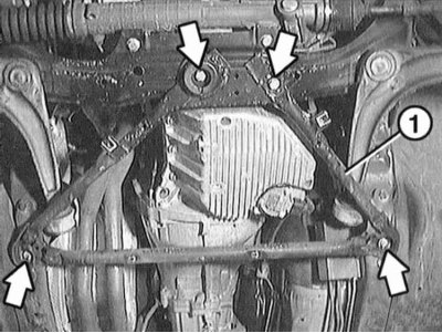
4. Unscrew the lower amplifier mounting bolts "1" (arrows in the illustration).
5. If there is a clearance sensor, disconnect it from the beam (arrow on the illustration).
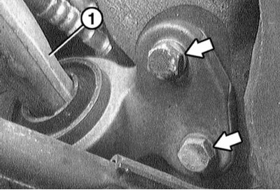
6. Disconnect the transverse arm "1" from the engine beam on the left and right (arrows in the illustration).
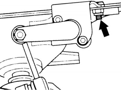
7. Unscrew the nuts (arrow on the illustration) left and right. Disconnect the ball joint of the transverse arm "1" using a plastic knuckle.
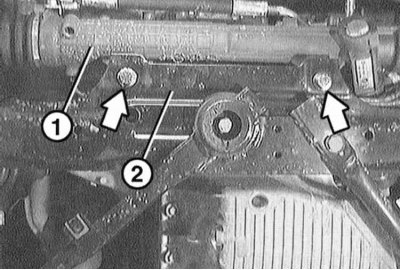
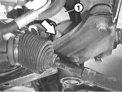
8. Loosen the mounting bolts and remove the steering gear "1" from the suspension beam "2" (arrows in the illustration).
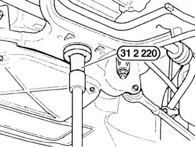
9. Place a garage lift with a wooden shim under the beam in the center. Support the beam.
The illustration shows an engine lift with a BMW-312220 spacer.
10. Loosen the bolts securing the suspension beam to the engine beam.
11. Carefully lower the beam using a garage lift.
Installation
12. Install the suspension beam and secure the engine beam with new bolts to the torque specified in the Specifications.
First, tighten both rear bolts, in relation to the "forward" direction.
13. Secure the steering gear to the suspension beam with new self-locking nuts to a torque of 42 Nm.
14. Clean the trunnion on the ball joint of the control arm and the hole in the suspension beam from grease. Insert the joint into the hole in the beam and press it upwards with the lift. This will make it easier to tighten the nut. The tightening torque is 80 Nm.
15. Secure the wishbone holder to the engine beam on the left and right with a torque of 60 Nm.
16. If the clearance sensor was removed, secure it to the suspension beam.
17. Tighten the lower reinforcement with bolts to a torque of 60 Nm.
18. Fasten the engine mount bolts to the engine beam with a torque of 47 Nm.
19. Install the lower engine compartment cover, refer to Section Removal and installation the lower engine compartment cover.
20. Remove the engine lifting device.
21. Install the front wheel so that the markings applied during removal match. Pre-lubricate the centering belt of the wheel disk on the hub with a thin layer of bearing grease. Do not lubricate the wheel mounting bolts. Replace rusty bolts. Tighten the bolts. Lower the car onto the wheels and tighten the bolts crosswise to a torque of 100 N·m.
22. Measure the geometric parameters of the chassis at a service station.
This article is available at russian, bulgarian, belarusian, ukrainian, serbian, croatian, romanian, polish, slovak, hungarian
Article verified: Sevastyanov Nikolay
Share information:
Previous articles
БМВ E46: Suspension front and rear
Next articles
Similar articles on other types of BMW cars:
Removal and installation the front axle beam BMW 5 Series E39 (1995-2003)
Removal and installation the front suspension strut assembly BMW 5 Series E28 (1981-1988)
Front suspension — removal and installation BMW 7 Series E32 (1986-1994)
Removal and installation the suspension beam BMW 7 Series E38 (1994-2001)
Removal and installation the airbag system module in the left or… BMW X3 E83 (2003-2010)
Removal and installation front door glass BMW X5 E53 (1999-2006)
Link in different formats to this page
Visitor comments
No comments yet
- General information
- Manual
- Maintenance
- Power unit
- Engine repair
- Cooling system
- Power system (gasoline)
- Injection system (gasoline)
- Fuel system (diesel)
- Exhaust system
- Ignition system
- Charge and launch systems
- Transmission
- Car gearbox
- Clutch and drive shafts
- Chassis
- Brake system
- Suspension front and rear
- Steering
- Body
- Body care and repair
- Exterior
- Interior
- Electrical equipment
- Troubleshooting
- Lighting and signaling
- Equipment and devices
- Heater and air conditioner
- Electrical circuits
- General information
- Manual
- Repair on the road
- Weekly checks
- Maintenance
- Troubleshooting
- Power unit
- 4 cylinder engines
- 6 cylinder engines
- Engine overhaul
- Cooling and heating
- Fuel and exhaust system
- Starting and charging system
- Ignition system
- Transmission
- Clutch
- Mechanical gearbox
- Automatic gearbox
- Cardan and drive shafts
- Chassis
- Brake system
- Wheel suspension
- Steering
- Body
- Exterior
- Interior
- Electrical equipment
- Equipment and devices
- Electrical circuits
- General information
- Maintenance
- Power unit
- Engine repair
- Cooling system
- Ignition system
- Supply system
- Fuel injection system
- Exhaust system
- Transmission
- Clutch
- Car gearbox
- Front and rear axle
- Chassis
- Steering
- Brake system
- Body
- Exterior
- Interior
- Electrical equipment
- Heating system
- Equipment and devices
- Power devices
- Electrical circuits
- Power unit
- M10/M20 engine
- M40 engine
- Ignition system
- Lubrication system
- Cooling system
- Supply system
- Fuel injection
- Exhaust system
- Transmission
- Clutch
- Manual gearbox
- Front axle
- Rear axle
- Chassis
- Steering
- Brake system
- Body
- Exterior
- Interior
- Electrical equipment
- Heating system
- Equipment and devices
- Electrical circuits
- General information
- Specifications
- Operation and maintenance
- 4-cylinder engine
- Engine repair
- Cooling and lubrication system
- Supply system
- Ignition system
- 6-cylinder engine
- Engine repair
- Cooling and lubrication system
- Supply system
- Fuel injection system
- Ignition system
- Transmission
- Clutch
- 4-speed manual gearbox
- 5-speed manual gearbox
- Automatic gearbox
- Cardan and rear axle
- Chassis
- Steering
- Front suspension
- Rear suspension
- Brake system
- Electrical equipment
- Equipment and devices
- Electrical circuits