



Table of contents: Fuel supply system ↓ Automatic starting device ↓ 1st phase of operation of the…↓ 2nd phase of operation of the…↓ Idle system and transition system of…↓ Acceleration ↓ Partial load mode ↓ Transition system of the 2nd chamber ↓ Full engine load mode ↓ Forced idle mode and engine shutdown ↓
- Home
- BMW 5 Series
- E12
- Power unit
- Ecotronic power supply system
- Description of mixture formation in the 2BE carburetor
Description of mixture formation in the 2BE carburetor (BMW 5 Series E12)
Fuel supply system
The constancy of the fuel level in each of the carburetor float chambers is ensured by regulating the action of the floats on the needle valves. The preparation of the fuel-air mixture and fuel consumption depend on the air pressure in the float chambers. In this regard, the carburetor cover has channels connecting the float chambers with the carburetor inlet, to which the air pressure purified in the air filter is supplied, i.e. the ventilation of the float chambers is closed. This achieves a virtually constant composition of the fuel-air mixture regardless of the degree of contamination of the air filter element. A shut-off valve is installed in front of the needle valve of the 2nd chamber, opening and closing under the action of vacuum. This valve prevents fuel leakage through the needle valve when the 2nd chamber is blocked at idle speed and at an average crankshaft speed.
Automatic starting device
The enrichment of the combustible mixture required for cold starting and warming up the engine is ensured by closing the air damper with a displaced axis, the amount of fuel-air emulsion is adjusted by the throttle valve of the 1st chamber. The idle air jet with a movable needle simultaneously ensures enrichment of the combustible mixture at idle and in transient modes. The jet needle is connected by a lever to the air damper axis.
The electronic idle speed control circuit compensates for the effects of incoming air and coolant temperature, atmospheric pressure and engine load.
The microprocessor of the controller processes the input signals and controls the actuator motors of the servo drives of the air damper and the throttle valve of the 1st chamber.
The cylinder filling correction signals are processed by the throttle valve of the 1st chamber, which is driven by an electropneumatic servo drive.
In the initial position (before turning on the ignition) automatic starting device controller, sensors and air damper servo drive are turned on, the air damper rests on the idle air jet needle, the throttle valve of the 1st chamber is completely closed under the action of the servo drive.
1st phase of operation of the automatic starting device (cold engine start)
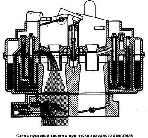
At the moment of engine start, the controller processes signals coming from the temperature sensors, the angular position of the throttle valve of the 1st chamber and the start of the countdown (engine speed), and sends control signals to the servo drives of the air damper and the throttle valve of the 1st chamber.
The air damper closes depending on the temperature. Under the action of the vacuum created in the space under the air damper, the fuel-air emulsion is sucked in through the main fuel jet, the idle fuel jet and the transition system. The degree of opening of the air damper, which has an offset axis, is regulated under the action of the vacuum depending on the engine crankshaft speed.
2nd phase of operation of the automatic starting device (engine warm-up)
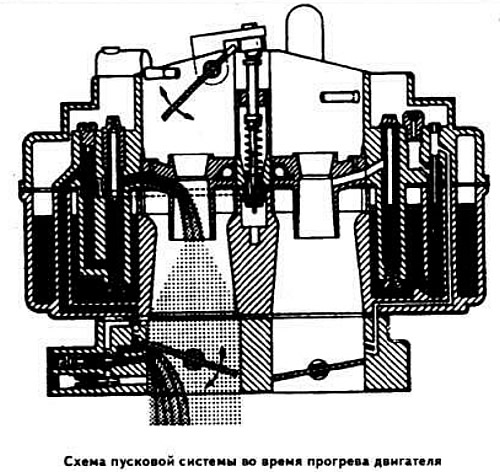
After starting the engine, in order to deplete the combustible mixture, the controller issues a command to reduce the closing moment of the air damper servo drive, which opens to the appropriate angle. To prevent excessive increase in the engine speed after starting, the controller issues a control signal to the throttle valve servo drive of the 1st chamber, which turns to the 8th side of closing.
At idle and in modes close to idle, at average coolant temperatures, the composition of the fuel-air mixture is regulated by moving the idle air jet needle depending on the position of the air damper.
Idle system and transition system of the 1st chamber
After the engine warms up, the air damper is open and enrichment of the combustible mixture stops. Based on the engine speed information, the controller issues a control signal to the throttle valve servo drive of the 1st chamber, which closes completely. The 2BE carburetor idle system operates in the same way as conventional carburetors. The fuel-air emulsion enters the transition system of the 1st chamber through the transition slot channel before the main metering system is turned on.
Acceleration
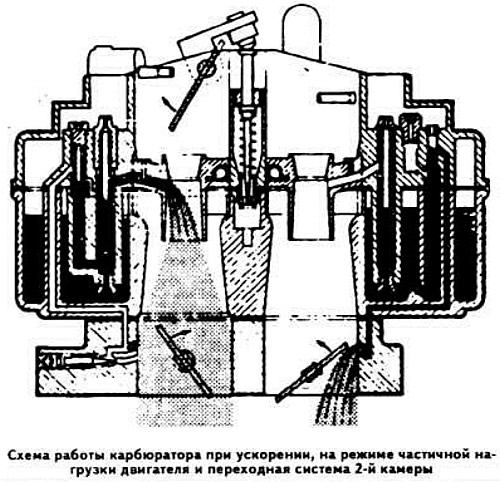
As the engine speed increases, the controller solves the problem of adapting the amount of fuel supplied to the carburetor with the growing amount of incoming air, i.e. when preparing the fuel-air mixture, it is necessary to compensate for the amount of fuel that condenses on the walls of the carburetor due to the increase in vacuum in the intake manifold.
In the 1st chamber, a pressure drop is created, the value of which depends on the duration and moment of closing. applied to the air damper by the servo drive according to the controller commands. As a result, the amount of fuel supplied to the main metering system through the main fuel jet increases. The degree of enrichment of the combustible mixture during acceleration depends on the temperature, engine speed, position and opening speed of the throttle valve of the 1st chamber.
The 2BE carburetor does not have an accelerator pump.
Partial load mode
At partial engine load, the main dosing system of the 1st chamber is switched on. The movement of the air damper for enrichment of the combustible mixture is carried out according to the program embedded in the controller, depending on the position of the throttle valve of the 1st chamber, which in turn depends on the number of revolutions and the engine load.
Transition system of the 2nd chamber
The throttle valve of the 2nd chamber is moved by the pneumatic drive, and the degree of its opening is determined by the opening angle of the throttle valve of the 1st chamber and the amount of air sucked in. A specially designed lever system ensures smooth opening of the throttle valve of the 2nd chamber, depending on the position of the locking lever, only after the throttle valve of the 1st chamber has opened by 2/3 of the full flow section. In order to prevent damage to the carburetor components, the throttle valve returns to its original state during the closing of the throttle valve of the 1st chamber. At the moment the throttle valve of the 2nd chamber begins to open, the transition system compensates for the activation of the main metering system. When the accelerator pedal is pressed so that the throttle valve has opened by more than 2/3, the throttle valve of the 2nd chamber opens. This causes a partial closure of the air damper according to the commands of the controller. Instant enrichment of the combustible mixture ensures a smooth transition to operation of the 2nd chamber in power modes.
At full engine load, the degree of opening of the throttle valve of the 2nd chamber is determined only by the amount of air sucked in, which in turn depends on the engine speed. The speed of opening of the throttle valve of the 2nd chamber is determined by the flow section of the damper nozzle installed in the intake manifold and controlled by means of a thermostatic valve.
Full engine load mode
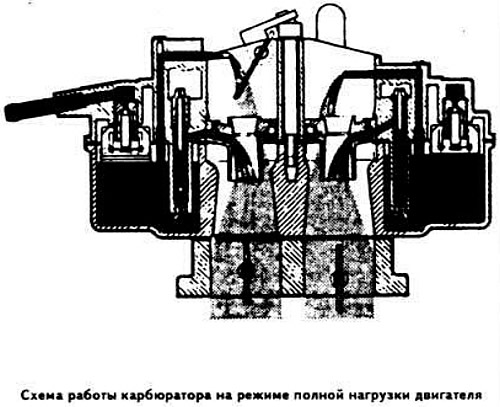
At full load and starting from intermediate engine modes, the main dosing systems and power mode economizers of the 1st and 2nd chambers are switched on. The power mode economizer tubes are in the vacuum zone located higher than the emulsion tubes of the main dosing systems. As a result, the power mode economizers are switched on only with a significant air inflow.
Forced idle mode and engine shutdown
When the crankshaft speed decreases, the throttle valve of the first chamber closes under the action of the servo drive. When the engine speed exceeds 1400 rpm, the fuel supply is interrupted. In this case, the emulsion outlet opening from the idle system is located above the edge of the throttle valve of the first chamber, i.e. in the atmospheric pressure zone, and the idle system is switched off.
When the ignition is switched off, the fuel supply stops, which makes it impossible for the engine crankshaft to continue rotating. At the same time, when the throttle valve of the 1st chamber is closed, the air valve of the engine braking system opens under the action of the vacuum in the intake manifold, which limits the vacuum in the intake manifold during engine braking at high speeds.
After opening this valve, the internal space of the air filter communicates with the intake manifold. Such purging promotes the afterburning of unburned gases in the exhaust tract.
This article is available at russian, bulgarian, belarusian, ukrainian, serbian, croatian, romanian, polish, slovak, hungarian
Article verified: Polikarpov Saveliy
Share information:
Previous articles
БМВ E12: Ecotronic power supply system
Next articles
Similar articles on other types of BMW cars:
Removal and installation of the Solex DIDTA 32/32 carburetor BMW 3 Series E21 (1975-1983)
Electrical diagram of the mixture preparation/ignition system BMW X5 E53 (1999-2006)
Removal and installation of the Solex DIDTA 32/32 carburetor BMW 3 Series E21 (1975-1983)
Electrical diagram of the mixture preparation/ignition system BMW X5 E53 (1999-2006)
Link in different formats to this page
Visitor comments
No comments yet
- General information
- Governing bodies
- Manual
- Maintenance
- Power unit
- Engine repair
- Lubrication system
- Cooling system
- Ignition system
- Supply system
- Injection system (gasoline)
- Injection system (diesel)
- Exhaust system
- Transmission
- Clutch
- Car gearbox
- Front axle
- Rear axle
- Chassis
- Steering
- Brake system
- Wheels and tires
- Body
- Interior
- Exterior
- Heating system
- Electrical equipment
- Equipment and devices
- Power devices
- Windscreen wipers
- Electrical circuits
- General information
- Manual
- Maintenance
- Power unit
- Engine repair
- Ignition system
- Engine lubrication system
- Cooling system
- Fuel system (gasoline)
- Fuel system (diesel)
- Exhaust system
- Transmission
- Clutch
- Car gearbox
- Chassis
- Front and rear suspension
- Steering
- Brake system
- Body
- Exterior
- Interior
- Electrical equipment
- Heating system
- Equipment and devices
- Power devices
- Electrical circuits
- General information
- Manual
- Maintenance
- Power unit
- Engine in a car
- Engine overhaul
- Cooling system
- Supply system
- Ignition system
- Control system
- Transmission
- Clutch
- Manual gearbox
- Automatic gearbox
- Transmission line
- Chassis
- Steering
- Front suspension
- Rear suspension
- Brake system
- Body
- Body elements
- Car care and painting
- Electrical equipment
- Heater and air conditioner
- Equipment and devices
- Starter and generator
- Electrical circuits
- General information
- Operation and maintenance
- Specifications
- Power unit
- Engine repair
- Cooling and lubrication system
- Supply system
- Ecotronic power supply system
- Fuel injection system
- Ignition system
- Transmission
- Clutch
- Gearbox BMW 242/4
- Gearbox Getrag 262/8
- Gearbox Getrag 265/6
- Automatic gearbox
- Cardan gear
- Rear axle
- Chassis
- Steering
- Front suspension
- Rear suspension
- Brake system
- Electrical equipment
- Equipment and devices
- Electrical circuits