Cars Mazda Cars Mitsubishi Cars Toyota Cars Chevrolet Cars AvtoVAZ Cars Kia Cars Nissan
English Русский
Български
Беларускі
Український
Српски
Hrvatski
Română
Polski
Slovenský
Magyar
| Articles | Contacts | Sitemap |   
BMWman.ru


3 series   5 series   7 series   BMW X3   BMW X5   BMW X6

E39 (1995-2003) E34 (1988-1996) E28 (1981-1988) E12 (1972-1981)
  • Home
  • BMW 5 Series
  • E12
  • Power unit
  • Engine repair
  • Installing the camshaft drive

Installing the camshaft drive (BMW 5 Series E12)

            0

Install the chain tensioner guide and shoe (see the figure "Camshaft Drive Diagram") and make sure that the shoe rotates freely around its axis.

Install the chain tensioner guide and shoe (see the figure «Camshaft Drive Diagram») and make sure…


Place the pulley on the crankshaft nose without tightening the pulley mounting nut. Set the piston of the 1st cylinder to the TDC position at the end of the compression stroke. In this case, the TDC mark on the pulley should be opposite the pointer (models "518", "520") or tide (models "525", "528") on the lower timing cover. Make sure this is done when installing the timing cover.

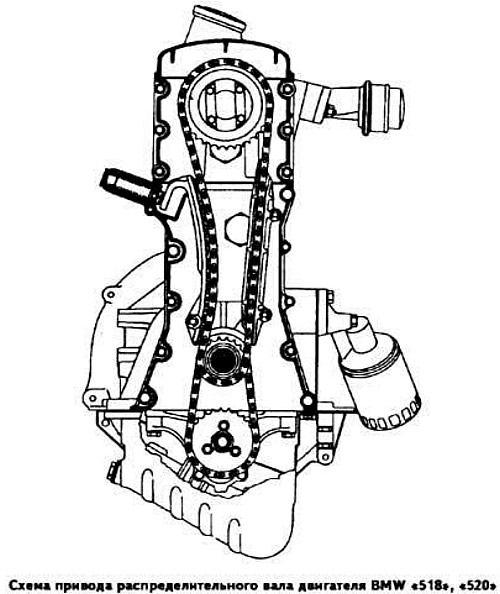
Insert the chain into the guide and place it on the crankshaft sprocket in accordance with the timing mark applied to the chain when it was removed.

Connect both branches of the chain with wire at the top of the damper.

Install the lower timing cover gasket and apply Atmosit type sealing paste to the lower mating surface of the cover.

Remove the crankshaft pulley without turning the shaft, then install the lower timing cover.

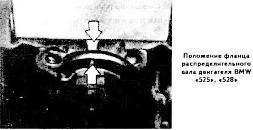
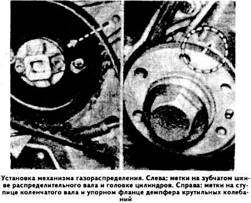
After assembling the cylinder heads (see "Cylinder head assembly") install the camshaft flange so that the dowel pin points downwards. In this case, the mark on the flange (models "518", "520") must be aligned with the installation lug on the cylinder head (see photo in the subsection "Installing the cylinder head"). On models "525" and "528" the flange locating pin should be offset at an angle of approximately 45° downwards and to the left.


The upper threaded hole must align with the mounting boss on the cylinder head (see picture).

The upper threaded hole must align with the mounting boss on the cylinder head (see picture).


Place a dry gasket on the cylinder head studs (the installation of the gasket is possible only in one position). Install the cylinder head. Tighten the mounting bolts in three stages in the specified order (see above).

Disconnect the chain branches and place it on the camshaft sprocket, aligning the holes in the pulley and in the camshaft flange (models "518", "520").

Disconnect the chain branches and place it on the camshaft sprocket, aligning the holes in the…


Tighten the camshaft sprocket mounting bolts and lock them by bending the locking plates.

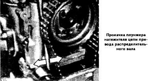
Pour engine oil into the recess of the upper timing cover to the level of the chain tensioner plunger. Bleed the chain tensioner as follows:
  • install the plunger and tensioner spring; in this case it is necessary to insert the front groove of the plunger into the bracket of the tensioner shoe and direct the spring with the conical part towards the plug;
  • partially tighten the tensioner plug;
  • press the tensioner shoe bracket several times with a screwdriver until oil starts to flow out of the plug;
  • wipe the cork and screw it on tightly.

wipe the cork and screw it on tightly.


Note: Causes of camshaft drive chain noise may include air in the plunger, plunger sticking, clogged plunger ventilation slots, faulty ball valve, excessively stiff or weak plunger spring, or sticking chain tensioner shoe bracket.


Install the upper timing mechanism drive cover, having previously applied a sealant such as Atmosit to its lower part.

Install the ignition distributor bracket. Set the ignition distributor in such a position that the rotor is opposite the mark on the distributor housing, and the piston of the 1st cylinder is at TDC of the end of the compression stroke.

Insert the segment keys into the sockets on the front end of the crankshaft, press in the new front crankshaft oil seal. Install the crankshaft pulley and secure it with a nut and washer, tightening it to a torque of 14.0-15.0 kgf·m.

Install the clutch, positioning the driven disk with the protruding part towards the pressure plate and center the disk relative to the flywheel with a mandrel.

Adjust the valve drive clearances. Install the removed components and assemblies onto the engine.

Stop the engine (or power unit) and install it on the car.

Since 1978 model year, engine disassembly and assembly "525", "528" and "528i" are produced taking into account the following:
  • when replacing the camshaft drive chain: remove the distributor cap; set the piston of the 1st cylinder to the TDC position, aligning the "OT" mark on the torsional vibration damper with the mark on the lower cover of the valve timing mechanism drive; the speed limiter must be directed towards the mark on the ignition distributor housing;
  • when replacing the crankshaft sprocket: remove the camshaft drive chain, oil pan, oil pump drive sprocket; remove the woodruff key and remove the oil seal from the crankshaft sprocket; press the sprocket with a puller 112000; replace the camshaft drive chain and the oil pump drive chain;
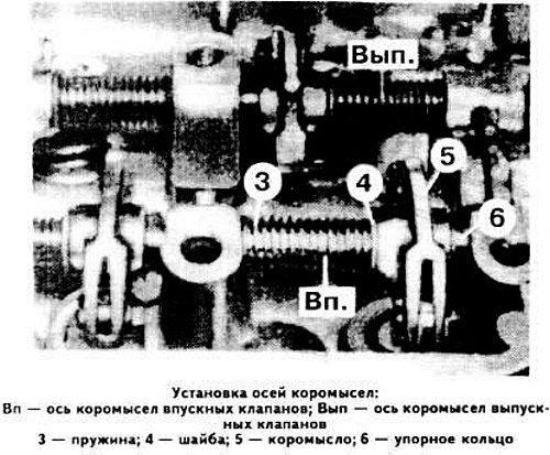
  • when replacing the valve rocker shafts: after removing the threaded plugs, screw in the 113060 tool (previously 7004); remove the mounting studs, press out the front valve rocker arm axles; installation is carried out in the following order: spring 3 (see photo), washer 4, rocker 5, thrust ring 6;
  • when replacing the valve rocker arms: install the calibrated screw 1 (see photo), eccentric 2, washer 3 and nut 4 on the new rocker arm. If the eccentric is worn, replace it.

when replacing the valve rocker arms: install the calibrated screw 1 (see photo), eccentric 2,…


when replacing the valve rocker arms: install the calibrated screw 1 (see photo), eccentric 2,…


when replacing the valve rocker arms: install the calibrated screw 1 (see photo), eccentric 2,…


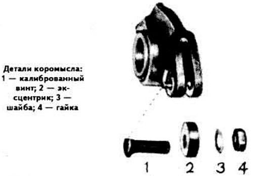
Note: The calibrated screw and nut have a thread of M6x0.75. The flat of the calibrated screw should be directed towards the back of the rocker arm.

This article is available at russian, bulgarian, belarusian, ukrainian, serbian, croatian, romanian, polish, slovak, hungarian
Article verified: Polikarpov Saveliy

Share information:
Previous articles
БМВ E12: Engine repair
Next articles

Checking the clearance between the bearings and the connecting rod…
Checking the axial clearance of the crankshaft
Checking the clearance between the bearing shells and the main…
Grinding the flywheel
Replacing the flywheel toothed rim
Exhaust system Details
Timing mechanism parts
Replacing the camshaft drive belt of the 6-cylinder BMW «520» and…


Similar articles on other types of BMW cars:
Installing the camshaft drive BMW 3 Series E21 (1975-1983)
Drive chain and sprockets — removal, inspection and installation BMW 7 Series E32 (1986-1994)
Final drive oil change BMW 7 Series E38 (1994-2001)
Generator drive belt BMW X3 E83 (2003-2010)
Installing the intake camshaft BMW X5 E53 (1999-2006)
Link in different formats to this page


Visitor comments

No comments yet


How much 18 + 31 =


BMW E39 (1995-2003) 
  • General information
  • Governing bodies
  • Manual
  • Maintenance
  • Power unit
  • Engine repair
  • Lubrication system
  • Cooling system
  • Ignition system
  • Supply system
  • Injection system (gasoline)
  • Injection system (diesel)
  • Exhaust system
  • Transmission
  • Clutch
  • Car gearbox
  • Front axle
  • Rear axle
  • Chassis
  • Steering
  • Brake system
  • Wheels and tires
  • Body
  • Interior
  • Exterior
  • Heating system
  • Electrical equipment
  • Equipment and devices
  • Power devices
  • Windscreen wipers
  • Electrical circuits
BMW E34 (1988-1996) 
  • General information
  • Manual
  • Maintenance
  • Power unit
  • Engine repair
  • Ignition system
  • Engine lubrication system
  • Cooling system
  • Fuel system (gasoline)
  • Fuel system (diesel)
  • Exhaust system
  • Transmission
  • Clutch
  • Car gearbox
  • Chassis
  • Front and rear suspension
  • Steering
  • Brake system
  • Body
  • Exterior
  • Interior
  • Electrical equipment
  • Heating system
  • Equipment and devices
  • Power devices
  • Electrical circuits
BMW E28 (1981-1988) 
  • General information
  • Manual
  • Maintenance
  • Power unit
  • Engine in a car
  • Engine overhaul
  • Cooling system
  • Supply system
  • Ignition system
  • Control system
  • Transmission
  • Clutch
  • Manual gearbox
  • Automatic gearbox
  • Transmission line
  • Chassis
  • Steering
  • Front suspension
  • Rear suspension
  • Brake system
  • Body
  • Body elements
  • Car care and painting
  • Electrical equipment
  • Heater and air conditioner
  • Equipment and devices
  • Starter and generator
  • Electrical circuits
BMW E12 (1972-1981) 
  • General information
  • Operation and maintenance
  • Specifications
  • Power unit
  • Engine repair
  • Cooling and lubrication system
  • Supply system
  • Ecotronic power supply system
  • Fuel injection system
  • Ignition system
  • Transmission
  • Clutch
  • Gearbox BMW 242/4
  • Gearbox Getrag 262/8
  • Gearbox Getrag 265/6
  • Automatic gearbox
  • Cardan gear
  • Rear axle
  • Chassis
  • Steering
  • Front suspension
  • Rear suspension
  • Brake system
  • Electrical equipment
  • Equipment and devices
  • Electrical circuits
BMWman.ru © 2017-2026 · Mobile version · News and articles · Sitemap: EN BG BY UA RS HR RO PL SK HU · Feedback · Site search
3er E21 · 3er E30 · 3er E36 · 3er E46 [petrol] · 3er E46 · 5er E12 · 5er E28 · 5er E34 · 5er E39 · 7er E32 · 7er E38 · X3 E83 · X5 E53 ·
This site uses cookies 🍪, without them some features simply would not work.