
Clean all bearing beds and camshaft lobes of the intake valves and lubricate them with engine oil. Intake camshaft (16, see Fig. 5.11) has a groove, and the wheel (17) of its position sensor has a protrusion for their mutual fixation.
Put on the wheel (17) of the sensor and align it with the groove in the camshaft. Insert and tighten the bolt (18, M16x1.5) torque of 30.0 N·m (3.0 kgf·m). Insert the rectangular rings (13), starting installation from the far ring. Be extremely careful, the rings break easily. Carefully spread the ends of the ring and install it in the groove. Press the end of the ring into the groove, and hook it with a clamp on the other side.
Insert the intake camshaft (16) so that the cams of the 5th cylinder point upwards.
Make sure the liners (1, Fig. 5.104) the eccentric shaft bearings are fixed in the support bridge.
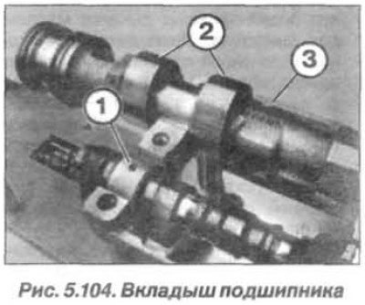
Note: The bearing shell (1) is installed in a groove in the bearing cap.
Check the centering bushings for damage and correct installation. Install the bearing caps "RE2–RE5", the device "11.9.473" and secure the support bridge and the bearing cap with a nut. Install the device "11.9.472" and adjust the bearing bed of the intake camshaft.
Install centering bushings (device "11.9.475") and adjust device "11.9.472" relative to bearing caps 2 and 3. Install devices "11.9.474" (fig. 5.105) and wrap them until they fit.
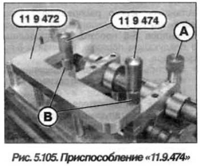
Note: Accessories "11.9.472", "11.9.474" and "11.9.475" remain installed until all torsion springs and intermediate arms are installed.
The installation of intermediate levers and torsion springs of cylinders 5–7 is similar to cylinder 8.
Install the "11.9.400" tool on one end of the 8th cylinder torsion spring and support the torsion spring on the cylinder head. Insert the bolt (M7) (1, see Fig. 5.101) and tighten it.
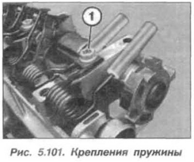
Lubricate all sliding surfaces of the intermediate levers with engine oil. Raise one end of the torsion spring using the "11.9.480" tool and remove the "11.9.490" tool from it. Hold one end of the torsion spring raised, install the intermediate lever with a movement from above. Insert the first end of the torsion spring into the guide on the intermediate lever.
Raise the other end of the torsion spring using the tool "11.9.480" and remove the tool "11.9.490" from it. Keep the other end of the torsion spring raised (see fig. 5.101), install the intermediate lever with a movement from above. Insert the second end of the torsion spring into the guide on the intermediate lever.
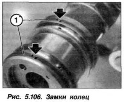
Install the eccentric shaft position sensor and remove the fixtures "11.9.474", "11.9.475". Make sure that the ends of the rings (1, Fig. 5.106) are directed upwards and their locks (arrows) snap into place.
Caution! The push rods move easily when installing the support bridge. Do not turn the support bridge over.
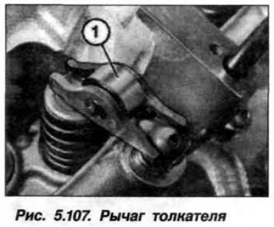
Make sure that the tappet lever (1) is fixed, as shown in Figure 5.107, on the elements of the hydraulic valve clearance compensation system and on their valves. Align the valve drive tappet levers (1). Remove the "11.9.473" tool and the "11.9.470" tool from the support bridge.
Install the support jumper (1, Fig. 5.97) with a top-down movement and carefully bring into contact with the cylinder head.
Install the nuts (M7, arrows) and wrap them by hand until they touch the support crossbar.
Caution! Make sure that the intermediate levers and pusher levers are in place and have not slipped.
Tighten the nuts (M7) from the middle to the edges, with a torque of 14 N·m (1.4 kgf·m). Install the bearing cover "RE1" so that the marking is read from the intake side. Install the nuts (M7, arrows) and tighten them to a torque of 14 Nm (1.4 kgf·m).
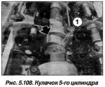
Turn the intake camshaft in the direction of rotation so that the cam of the 5th cylinder takes the inclined upper position, as shown in Figure 5.108 (arrow).
Install the left VANOS intake and exhaust actuators. Screw in the spark plugs for cylinders 5–8. Install the left cylinder head cover and the ignition coils for cylinders 5–8. Install the left eccentric shaft drive motor and assemble the engine.