
Table of contents: Removal the exhaust camshaft ↓ Installing the exhaust camshaft ↓
- Home
- BMW X5
- E53
- N62 petrol engine
- Engine repair
- Replacing the left exhaust camshaft
Replacing the left exhaust camshaft (BMW X5 E53)
Note. The technology for removing and installing the left exhaust camshaft is different. Prepare a "cash register" for laying out the parts to be removed by cylinder numbers.
Removal the exhaust camshaft
Removal of the left exhaust camshaft on cylinder bank 5–8 must be carried out in the following order.
Remove the left eccentric shaft drive motor, ignition coils for cylinders 5–8, left cylinder head cover, unscrew spark plugs for cylinders 5–8 and left VANOS actuators.
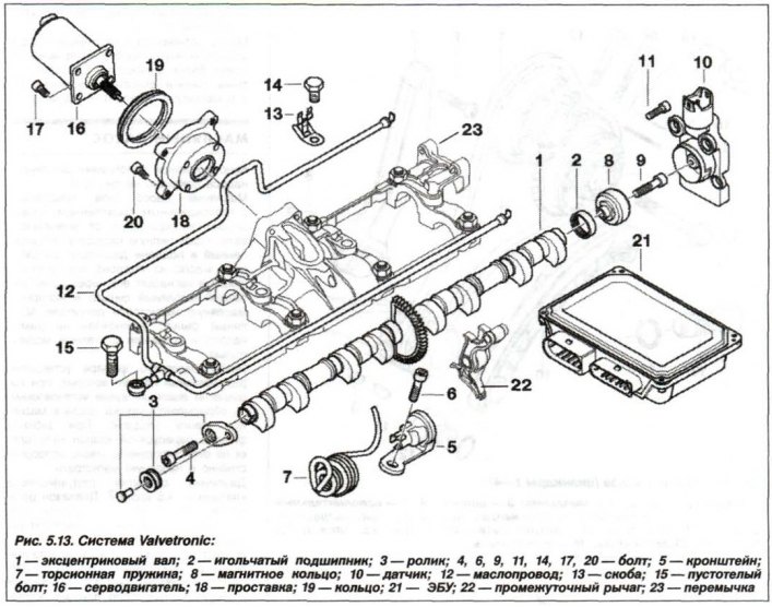
Mark the chain guide bar mounting bolts, as they are different – M8x50 and M6x70. Remove the bar (15, see Fig. 5.13) upper chain guide.
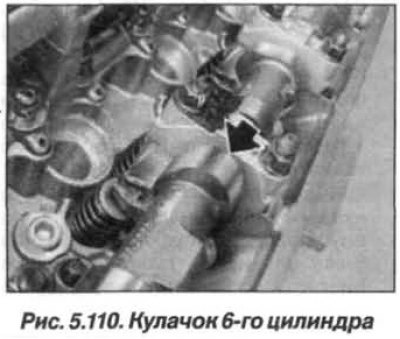
Turn the exhaust camshaft by the hexagon so that the cam of the 6th cylinder (arrow, Fig. 5.110) stood with his nose up.
Attention!
- Bearing caps for camshafts 1–4 and 5–8 must not be interchanged.
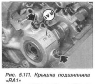
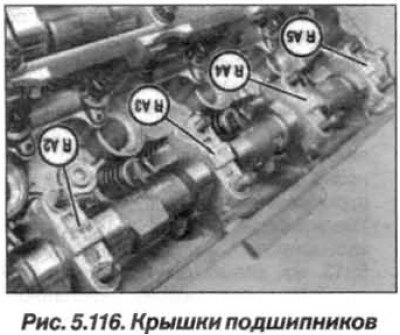
- The bearing caps of the exhaust camshaft of cylinders 5–8 are marked "RA1–RA5", read from the intake side.
Unscrew the nuts (arrows, Fig. 5.111) fasteners and remove the bearing cover "RA1". The oil line clamps are installed on the bearing covers 3 and 5.
Unscrew the nuts of the bearing caps "RA2–RA5", remove them and the exhaust camshaft.
Inspect the intake camshaft and replace the rings if necessary (1, see Fig. 5.106) rectangular cross-section, as they break easily. The rings (1) of rectangular cross-section snap into place at the joint.
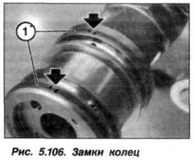
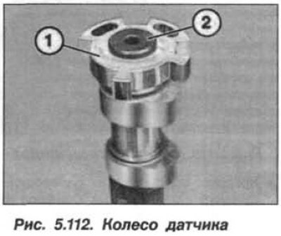
To remove the ring, press it into the groove on one side and pull it up on the other side and release the lock. Carefully spread the ring and remove it forward. Replace the wheel if necessary (1, Fig. 5.112) camshaft position sensor, for which unscrew the bolt (2) and remove the sensor wheel (1).
Installing the exhaust camshaft
The installation of the left exhaust camshaft on cylinder bank 5–8 must be carried out in the following order.
Clean all bearing beds and intake camshaft lobes and lubricate them with engine oil.
The exhaust camshaft has a groove, and the wheel of its position sensor has a protrusion for their mutual fixation. Put on the wheel of the speed sensor and adjust it relative to the groove in the camshaft. Insert and tighten the bolt (M14x1.5) with a torque of 30 N·m (3.0 kgf·m).
Carefully insert the rectangular rings, as they break easily. Carefully spread the ends of the ring and install it in the groove. Press the end of the rectangular ring into the groove and hook it with a lock on the other side. They snap into place at the joint.
Pusher levers (1, Fig. 5.113) the exhaust camshaft tappet levers have the same design as the intake camshaft tappet levers. The tappet lever classification does not affect the operation of the exhaust camshaft. The tappet levers (1) are easily displaced when installing the exhaust camshaft.
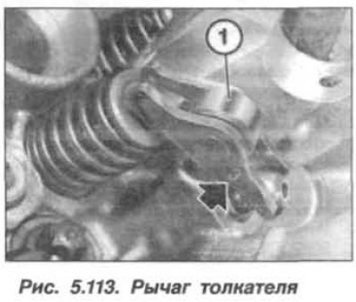
Make sure that the pushrod lever (1) is fixed, as shown in Figure 5.113, on the elements of the hydraulic valve clearance compensation system and on the valves.
Used tappet arms may only be reused in the same locations. Align the tappet arms in a straight direction. Lubricate the exhaust camshaft and bearing caps with engine oil.
Insert the exhaust camshaft (1, Fig. 5.114) into the cylinder head.
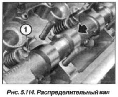
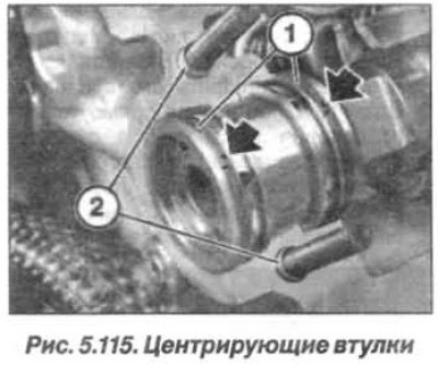
Turn the exhaust camshaft so that the cam of the 6th cylinder is with the nose up. Check the centering bushings (2, Fig. 5.115) for damage and correct installation. The ends of the rings (1) of rectangular cross-section, their locks, should be directed upwards. Make sure that the ends of the rings snap into place.
The exhaust camshaft bearing caps on cylinder bank 5–8 are marked "RA1–RA5" (fig. 5.116), readable from the intake side. Install bearing caps "RA2–RA5". Oil line clamps are installed on bearing caps 3 and 5.
Install the nuts and tighten them by hand until they fit. Tighten the nuts (M7) of the bearing caps "RA2–RA5" evenly, in several half-turn steps, from the middle to the edges, with a final torque of 14 N·m (1.4 kgf·m).
Install the bearing cover "RA1" so that its markings can be read from the intake side. Install the cover mounting nuts and tighten them to a torque of 14 N·m (1.4 kgf·m).
Replace the sealing gasket (16, Fig. 5.13) between the cylinder head and the chain guide bar.
Set the bar (15, see Fig. 5.13) chain guide with a new sealing gasket, insert and tighten the bolts (15, 16), which are different from each other.
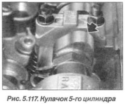
Turn the exhaust camshaft against the direction of its rotation so that the cam of the 5th cylinder is inclined upward, as shown in Figure 5.117 (arrow).
Install the left VANOS intake and exhaust actuators, screw in the spark plugs for cylinders 5–8, install the left cylinder head cover and the ignition coils for cylinders 5–8. Assemble the engine.
This article is available at russian, bulgarian, belarusian, ukrainian, serbian, croatian, romanian, polish, slovak, hungarian
Article verified: Zhuravleva Isolda
Share information:
Previous articles
БМВ E53: Engine repair
Next articles
Similar articles on other types of BMW cars:
Checking the level and replacing the oil in the automatic transmission BMW 3 Series E21 (1975-1983)
Replacing the camshaft drive belt of the 6-cylinder BMW «520» and… BMW 5 Series E12 (1972-1981)
Replacing the oil filter (center bolt design) BMW 7 Series E32 (1986-1994)
Replacing the cabin filter (ventilation system) BMW 7 Series E38 (1994-2001)
Replacing the exhaust camshaft BMW X3 E83 (2003-2010)
Link in different formats to this page
Visitor comments
No comments yet
- General information
- Manual
- Maintenance
- M54 petrol engine
- Engine repair
- Lubrication system
- Cooling system
- Supply system
- Injection system
- Exhaust system
- Engine electrics
- M62 petrol engine
- Engine repair
- Lubrication system
- Cooling system
- Supply system
- Exhaust system
- Engine electrics
- N62 petrol engine
- Engine repair
- Cooling and lubrication system
- Power and exhaust system
- Engine electrics
- Diesel engine M57
- Engine repair
- Lubrication system
- Cooling system
- Power and exhaust system
- Engine electrics
- Turbocharging system
- Transmission
- Clutch
- Mechanical gearbox
- Automatic gearbox
- Transfer case and cardan
- Chassis
- Brake system
- Steering
- Front suspension
- Rear suspension
- Wheels and tires
- Body
- Exterior
- Interior
- Doors and windows
- Repair and maintenance
- Heater and air conditioner
- Electrical equipment
- Equipment and devices
- Levers and switches
- Electrical circuits