
Prepare fixtures «11.9.190», «11.9.461» And «11.9.462». Remove the left eccentric shaft drive motor, left cylinder head cover. Unscrew all spark plugs for cylinders 5-8 and remove fan shroud.
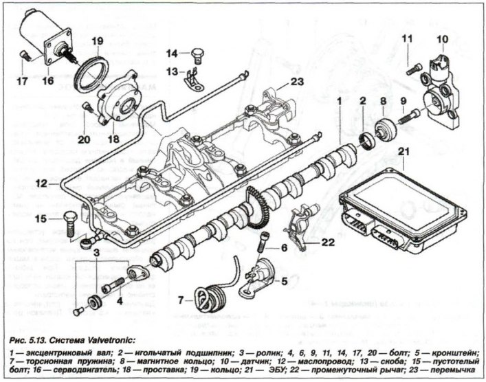
Screw in the special bolt (15, see fig. 5.13) . Release the oil line (12) from the clamps and remove it.
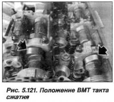
Turn the crankshaft at the central bolt in the direction of rotation until the piston of the 1st cylinder is at top dead center (TDC) the end of the compression stroke. In the TDC position of the end of the compression stroke of the 1st cylinder, the camshaft cams of the intake and exhaust valves of the 5th cylinder are inclined upwards, as shown in Figure 5.121.
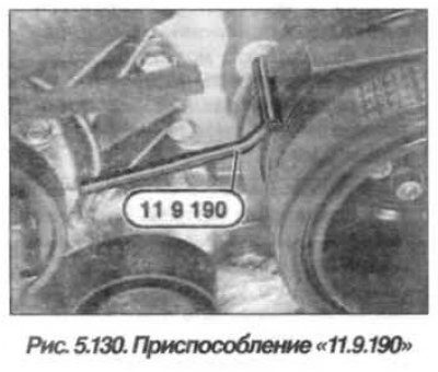
In the TDC position, fix the vibration damper with the tool «11.9.190» (pin), which is installed in the hole located on the timing cover (see fig. 5.130).
Attention! When the engine is stopped normally, the intake and exhaust actuators are blocked in their original position. In some cases, this initial position may not be reached and the camshaft rotates within the adjustment range of the assembly.
To avoid incorrect adjustment of the valve timing, it is necessary to check the locking of the actuator and, if necessary, block it by turning the camshafts.
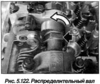
Check the blocking of the inlet control unit in the initial position. Grab the hexagon (dark arrow, fig. 5.122) intake camshaft and carefully try to turn the intake camshaft against the direction of rotation (light arrow).
If there is no reliable connection between the intake camshaft and the intake adjustment unit, turn the intake camshaft against the direction of rotation as far as it will go.
The intake actuator is locked in the home position if the intake camshaft is securely connected to the intake actuator.
Check the blocking of the actuating unit of the release in the initial position. To do this, grasp the exhaust camshaft hexagon and carefully try to turn the exhaust camshaft in the direction of rotation. If there is no good connection between the exhaust camshaft and the exhaust adjustment unit, turn the exhaust camshaft against the direction of rotation as far as it will go.
The exhaust actuator is locked in its home position if the exhaust camshaft is securely connected to the exhaust actuator.
Attention! If the inlet or outlet control unit «does not allow» block the camshafts as described, the adjustment unit is defective and must be replaced.
Install fixture «11.9.461» (pic. 5.123) on the intake camshaft and check the valve timing.
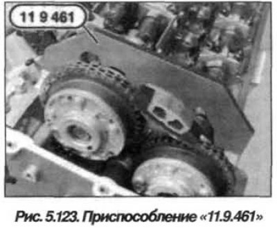
The valve timing is set correctly if the tool «11.9.461» is flush with the cylinder head or is raised by a maximum of 0.5 mm relative to the exhaust side.
Remove tool «11.9.461» from the intake camshaft and install the tool «11.9.462» on the exhaust camshaft and check the valve timing.
The valve timing is set correctly if the tool «11.9.462» is flush with the cylinder head or is raised by a maximum of 0.5 mm relative to the exhaust side.
If necessary, adjust the valve timing on the left side. Remove all fixtures.
Bolt (15, see fig. 5.13) is a special bolt and cannot be replaced with an ordinary M8 bolt. Clamp oil line (12) staples. Insert bolt (15) and tighten it. Assemble the engine.