
Prepare fixtures «11.9.470» And «11.9.473». Remove the motor for adjusting the left eccentric shaft and the ignition coils of cylinders 5-8. Remove left cylinder head cover, unscrew spark plugs for cylinders 5-8 and left intake and exhaust VANOS control units.
Attention! Rotate the intake camshaft so that when the support bridge is removed, the intermediate levers do not slip off and damage the camshaft.
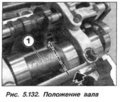
Turn the intake camshaft against the direction of rotation so that the inscription (1, fig. 5.132) was turned upwards in the direction of the axis of the 8th cylinder, and the cam (arrow) stood up horizontally.
The inlet camshaft bearing caps on cylinder bank 5-8 are marked «RE1–RE5», read from the intake side. Loosen the fastening nuts (arrows, fig. 5.133) and remove the bearing cap «RE1».

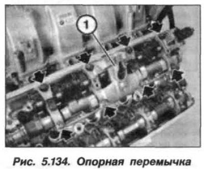
Loosen and remove eight nuts (arrows, fig. 5.134) support jumper fastenings (1), starting with the outer nuts and moving towards the center.
Attention!
- When removing the support bridge, do not turn it over.
- Pusher levers are divided into tolerance classes.
- On the intake side, only one tolerance class may be installed per cylinder. Tolerance classes are indicated by numbers from 1 to 4.
- Old class 1 and 2 match new «2a», class 3 and 4 – «2b».
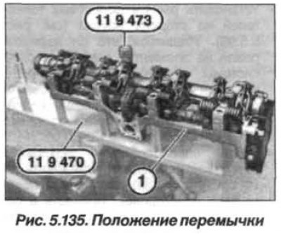
Clamp fixture «11.9.470» in a vice. Carefully remove support bar from cylinder head towards top. Do not overturn the support bridge and lay the support bridge together with the intake camshaft and the eccentric shaft, as shown in Figure 5.135, on the tool «11.9.470». Fix the support bar (1) nut (fixture «11.9.473»).
Attention! The lower part of the support bridge is machined together with the cylinder head and therefore cannot be repositioned. It remains on the cylinder head.
The removal of the intermediate levers should begin with the 8th cylinder, for cylinders 5–7 the steps are similar. The removal of the intermediate levers should begin with the 8th cylinder, for cylinders 5–7 the steps are similar.
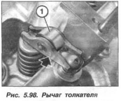
Remove levers (1, see fig. 5.98) roller tappets on the intake side and stack them in order.
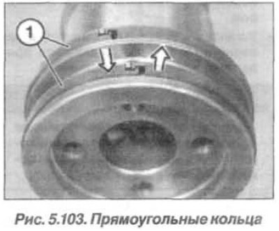
Inspect intake camshaft, replace rings if necessary (1, see fig. 5.103) rectangular section, because they break easily. Rings (1) rectangular cross-section snap into place at the junction. To remove the ring, press it on one side (left arrow) into the groove, and on the other hand pull up (right arrow) and release the latch. Carefully spread the ring (1) and remove it forward.
Installation of the intake camshaft pusher lever on the bank of cylinders 5-8 must be carried out in the following order, starting from the 8th cylinder.
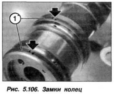
Clean all bearing beds and intake camshaft lobes and lubricate them with engine oil. Insert rectangular rings. Start the installation from the far ring. Be extremely careful, rings break easily. Carefully spread the ends of the ring and install it into the groove. Press the end of the rectangular ring into the groove, and on the other hand, hook it with a retainer. Make sure that the ends of the rings are pointing up and their locks are latched (see fig. 5.106).
Attention! The pusher arms are easy to move when installing the support bridge. Do not turn over the support bar.
Install the roller tappet arms on the intake side (see fig. 5.98). Make sure it is fixed on the elements of the hydraulic valve clearance compensation system and on their valves. Align the valve lifters and remove the tool «11.9.473» (see fig. 5.135).
Remove tool «11.9.470» from the reference jumper, install it (1, see fig. 5.134) from top to bottom and carefully bring it into contact with the cylinder head. Set nuts (M7) and wrap them by hand until they touch the support jumper.
Attention!
Make sure that the intermediate levers and pusher levers are in place and have not slipped.
The bearing caps for the camshafts of cylinders 1-4 and 5-8 must not be interchanged.
Tighten nuts (M7) from the middle to the edges, torque 14 Nm (1.4 kgf·m).
Install the bearing cover «RE1» so that the marking (see fig. 5.133) read from the intake side. Set nuts (M7) and tighten them to 14 Nm (1.4 kgf·m).
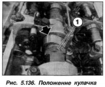
Turn the intake camshaft in the direction of rotation so that the cam of the 5th cylinder is in an inclined upward position (arrow, fig. 5.136), as it shown on the picture.
Marking (1) on the hexagon of the intake camshaft is located on top.
Install the left-hand intake and exhaust VANOS control units, screw in the spark plugs for cylinders 5-8, install the cover for the left-hand cylinder head and the ignition coils for cylinders 5-8.
Install the left eccentric shaft drive motor and assemble the motor.