
Note: The sequence of operations for removing and installing the VANOS actuators is different.
Removal of the left-hand VANOS intake and exhaust control units on cylinder bank 5–8 must be carried out in the following order.
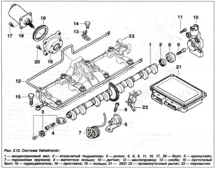
Prepare the equipment "11.9.190", "11.9.460", "11.9.461", "11.9.462" and "11.9.463". Read information from the fault memory device (FMD) and record it (record). Remove the left eccentric shaft adjustment drive motor, the left cylinder head cover of the engine, and unscrew the spark plugs of cylinders 5–8.
Remove the fan shroud, left timing belt cover and unscrew the special bolt (M8) (15, see Fig. 5.13), which cannot be replaced with a normal bolt. Release the oil line (12) from the clamps and remove it.
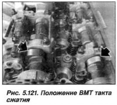
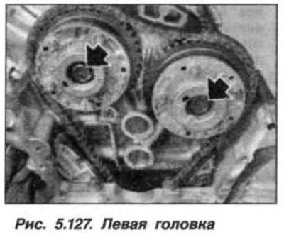
Turn the crankshaft by the central bolt in the direction of rotation to the TDC position of the end of the compression stroke in the 1st cylinder. In this case, the cams (arrows, see Fig. 5.121) the intake and exhaust valves of the 5th cylinder are positioned at an angle upward and outward, as shown in the figure.
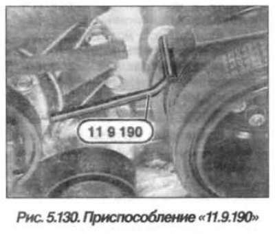
Fix the torsional vibration damper using the device "11.9.190" (see fig. 5.130) when the piston of the 1st cylinder is at TDC at the end of the compression stroke. The hole for the device is located on the front timing belt cover.
Attention! When the engine is stopped normally, the intake and exhaust actuators are locked in their original position.
In some cases, this initial position may not be reached and the camshaft rotates in the adjustment range of the actuator. To avoid incorrect adjustment of the valve timing, it is necessary to check the locking of the actuator and, if necessary, lock it by turning the camshaft.
Check the locking of the intake actuator in the initial position:
- take hold of the hexagon (dark arrow, see Fig. 5.122) intake camshaft and carefully try to turn the intake camshaft against the direction of rotation;
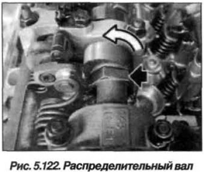
- if there is no reliable connection between the intake camshaft and the intake actuator (there is some play), it is necessary to turn the intake camshaft against the direction of rotation until it stops (light arrow);
- the intake actuator is considered to be locked in the initial position if the intake camshaft is securely connected to the intake actuator.
Check the locking of the release actuator in the initial position:
- take hold of the hexagon of the exhaust camshaft and carefully try to turn the exhaust camshaft in the direction of rotation;
- if there is no reliable connection between the exhaust camshaft and the exhaust actuator (there is some play), it is necessary to turn the exhaust camshaft in the direction of rotation until it stops;
- the exhaust actuator is considered to be locked in the initial position if the exhaust camshaft is securely connected to the exhaust actuator.
Attention. Very important! If the intake or exhaust actuator "does not allow" the camshafts to be locked in the manner described above, then the actuator is faulty and must be replaced.
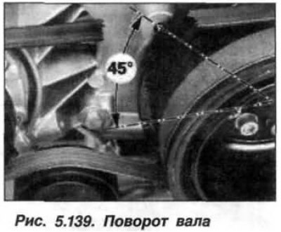
Remove the device "11.9.190". Turn the crankshaft by the central bolt against the direction of rotation to the position 45° before TDC (fig. 5.139).
Note: When unscrewing the bolts securing the actuator assemblies, hold the camshafts from turning using the hexagon.
Loosen the bolts (M10) (arrows, see Fig. 5.127) vANOS actuator fastenings. Loosen the VANOS exhaust actuator fastening bolt. Press the chain tensioner bar several times with force to remove the oil from it. Remove the exhaust actuator (2).
Loosen the bolt of the VANOS intake control unit. Remove the intake control unit, taking measures to prevent the drive chain from slipping by securing it to the engine head with a wire clip.
The installation of the left-hand VANOS intake and exhaust control units on cylinder bank 5–8 must be carried out in the following order.
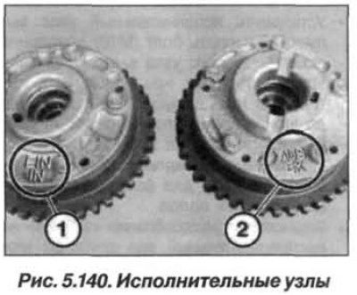
Caution! The intake and exhaust actuators are different, changing the installation locations of the intake and exhaust actuators of the VANOS system will damage the engine.
Intake control unit (1, Fig. 5.140) has the marking "EIN" and "IN", the actuator release unit (2) has the marking "AUS" and "EX".
The position of the intake actuator relative to the drive chain is arbitrary. Pull the drive chain up. Hook the sprocket of the intake actuator onto the drive chain and put the unit on the intake camshaft. Replace the bolt (M10) securing the actuator with a new one. Install the bolt securing the intake actuator and screw it in until the bolt head touches the unit. Unscrew the bolt by half a turn.
Position of the actuator release unit (2, Fig. 5.141) relative to the drive chain is arbitrary.
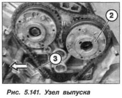
Pull the drive chain up. Hook the sprocket of the exhaust actuator onto the drive chain. Press the tensioner bar and put the exhaust actuator onto the exhaust camshaft.
If the tensioner bar is not pressed back enough to allow the release actuator to be installed, then it is necessary to:
- remove chain tensioner;
- place it on a flat surface and squeeze it slowly and gently, repeat this process twice;
- when installing the tensioner, it is necessary to replace the sealing ring, insert the tensioner and tighten it to a torque of 65 N·m (6.5 kgf·m).
Install the exhaust actuator. Replace the bolt (M10) securing the exhaust actuator with a new one. Install the exhaust actuator bolt and screw it in until the bolt head touches the assembly. Loosen the bolt by half a turn.
Prepare a set of tools "11.9.460" for fixing the camshafts.
Install the "11.9.461" tool on the intake camshaft and adjust the intake camshaft so that the "11.9.461" tool fits onto the cylinder head without gaps.
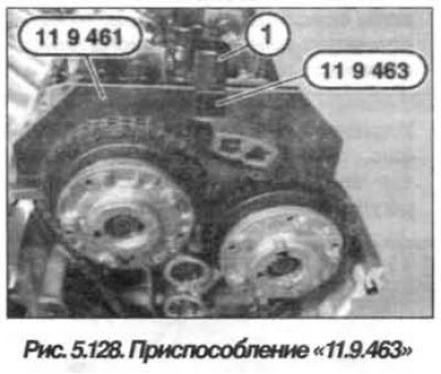
Install the device "11.9.463" by screwing in its screw (1, see Fig. 5.128) into the threaded hole for the oil line and tighten it by hand.
Attention! Make sure once again that the bolts securing the intake and exhaust actuators are loosened by half a turn.
Turn the crankshaft by the central bolt from the position 450 before the TDC of the end of the compression stroke, to the position of the piston of the 1st cylinder at the TDC of the end of the compression stroke. Fix the torsional vibration damper using the device "11.9.190" (see fig. 5.130) when the piston of the 1st cylinder is at TDC at the end of the compression stroke.
Tighten the new intake manifold assembly mounting bolt to a torque of 90 N·m (9.0 kgf·m), while holding the camshaft from turning by the hexagon.
Remove the bolt (1, see Fig. 5.128), remove tools "11.9.463" and "11.9.461" from the intake camshaft.
Install the "11.9.462" tool on the exhaust camshaft and adjust the exhaust camshaft so that the "11.9.462" tool fits onto the cylinder head without gaps.
Install the device "11.9.463" by screwing its screw into the threaded hole for the oil line and tightening it by hand.
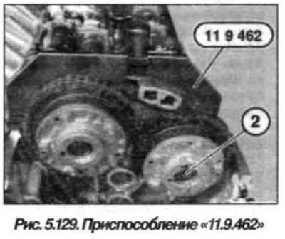
Tighten the new bolt (2, see Fig. 5.129) fastening the exhaust actuator with a torque of 90.0 N·m (9.0 kgf·m), while holding the camshaft from turning by the hexagon.
Loosen the bolt and remove tools "11.9.463" and "11.9.462" from the exhaust camshaft.
Remove the device "11.9.190" (see fig. 5.130). Turn the crankshaft by the central bolt in the direction of rotation by two full turns (720°) until the piston of the 1st cylinder is again set to the TDC position at the end of the compression stroke. Install the device "11.9.190", fixing the torsional vibration damper with the piston of the 1st cylinder in the TDC position at the end of the compression stroke.
Install the "11.9.461" tool on the intake camshaft and check the valve timing adjustment.
Note: The valve timing is adjusted correctly if the "11.9.461" tool fits against the cylinder head without gaps, or is raised relative to the exhaust side by a maximum of 0.5 mm.
Remove tool "11.9.461" from the intake camshaft and install tool "11.9.462" (fig. 4.142) on the exhaust camshaft and check the valve timing adjustment.
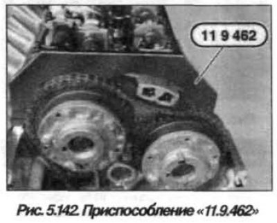
Note: The valve timing is adjusted correctly if the "11.9.462" tool fits against the cylinder head without gaps, or is raised relative to the exhaust side by a maximum of 0.5 mm.
Remove all fixtures. Clamp the oil line (12, see Fig. 5.13) brackets (3). Bolt (15) is a special bolt and cannot be replaced with a regular M8 bolt. Insert and tighten it. Assemble the engine.
(The original entry can be found on the portal: BMWMAN.ru)