Note. The technology for removing and installing intermediate levers is different.
Prepare fixtures «11.9.470», «11.9.472», «11.9.473», «11.9.474», «11.9.475», «11.9.480» And «11.9.490» And «checkout» for laying out parts to be removed by cylinder numbers. The removal of the intermediate levers in the left head of the block on the bank of cylinders 5-8 must be carried out in the following order.
Remove the motor for adjusting the left eccentric shaft, the ignition coils of cylinders 5-8, the cover of the left cylinder head and unscrew the spark plugs of cylinders 5-8. Remove left intake and exhaust VANOS adjustment units.
Attention, very important! First you need to rotate the intake camshaft so that when the support jumper is removed, the intermediate levers do not slip off and damage the camshaft.
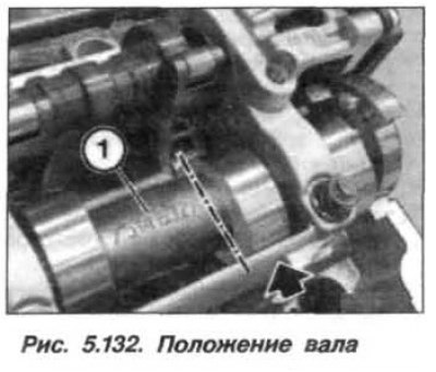
Turn the intake camshaft against the direction of rotation so that the inscription (1, see fig. 5.132) was turned upwards in the direction of the axis of the 8th cylinder, and its cam took a horizontal position.
Attention! The bearing caps for the camshafts of cylinders 1-4 and 5-8 must not be interchanged.
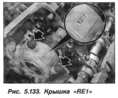
The inlet camshaft bearing caps on cylinder bank 5-8 are marked «RE1–RE5», read from the intake side.
Loosen the fastening nuts (arrows, see fig. 5.133) and remove the bearing cap «RE1».
Loosen and remove eight nuts (arrows, see fig. 5.134) support jumper fastenings (1), starting with the outer nuts and moving towards the center.

Attention!
- When removing the support bridge, do not turn it over.
- Pusher levers are divided into tolerance classes.
- On the intake side, only one tolerance class may be installed per cylinder. Tolerance classes are indicated by numbers from 1 to 4.
- Pusher levers have new class markings.
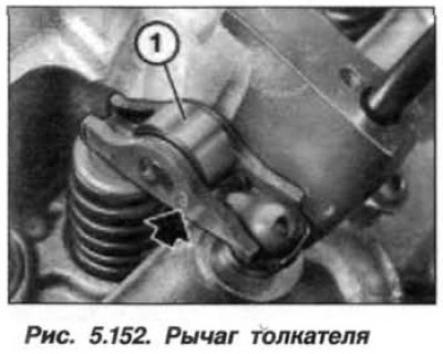
After removal of the jumper by the support, the roller levers of the pushers become accessible. Levers (1, fig. 5.152) Do not remove intake side tappets.
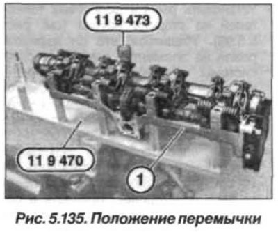
Clamp fixture «11.9.470» in a vice. Carefully remove support bar from cylinder head towards top. Do not turn over the support bar.
Lay the support bar (1, see fig. 5.135) together with the intake camshaft and eccentric shaft, as shown in the figure, onto the tool «11.9.470».
Note. Removal of intermediate levers should be started from the 8th cylinder, for 5–7 cylinders the actions are similar.
Further technology for replacing the intermediate levers in the left head of the block is discussed above, in the section «Replacing the tappet levers on the intake side of the left cylinder head».
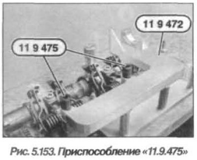
When installing the intermediate levers, it is necessary to fix the intake camshaft in the axial direction, for which install the tool «11.9.472» and fix it with a tool «11.9.475» (pic. 5.153), which prevents the intake camshaft from rotating and shifting when the pusher arms are installed.