
Attention!
- The eccentric shafts on cylinder side 1-4 and 5-8 of the engine produced since September 2003 are identical and differ in the installation location of the magnetic wheel, and they must not be interchanged. Incorrect installation of the shafts leads to engine damage.
- The needle bearing is very easily damaged, so be extremely careful when removing and installing it.
- The technology for performing operations on installing and removing eccentric shafts has its own characteristics.
- If needle bearings are replaced, their liners must also be replaced.
The left eccentric shaft on cylinder side 5–8 must be removed in the following order: Remove the left eccentric shaft drive motor, the ignition coils of cylinders 5–8, unscrew the spark plugs of cylinders 5–8, remove the left cylinder head cover, the left VANOS intake and exhaust actuators, and remove the left intake camshaft.
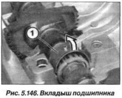
Carefully fold back the insert (1, Fig. 5.146) bearing to the side and simultaneously remove it by moving it upwards (arrow). Remove all other bearing shells of the eccentric shaft as described above. Remove the eccentric shaft. Carefully clamp it in a vice with soft jaws.
Attention! Very important! It is very easy to confuse the left and right eccentric shafts or their front and rear ends.
If necessary, you can remove the magnetic wheel, but you must take into account that it is very strongly magnetized.
Apply color marks to the ends where the magnetic wheel was installed. Unscrew the bolt, remove the magnetic wheel and put a plastic cover on it to protect it from metal dust.
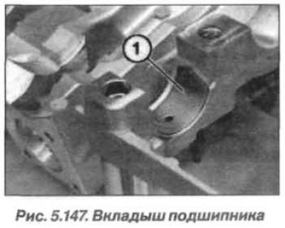
Carefully push the needle bearing apart at the separation point just enough to remove it from the eccentric shaft. Carefully press the bearing shell (1, Fig. 5.147) bearing to the side and simultaneously remove it with an upward movement.
Before installation, lubricate the eccentric shaft at the bearing bed locations. Replace the needle bearing by carefully pushing it apart at the separation point just enough to allow it to be installed on the eccentric shaft.
Caution! The eccentric shafts on cylinder side 1-4 and 5-8 are the same. Incorrect installation of the shaft will result in engine damage.
Pay attention to the position of the eccentric shafts during installation. They are installed depending on which side of the eccentric shaft of cylinders 1–4 and 5–8 the magnetic wheel is installed on.
Clamp the eccentric shaft in a vice with soft jaws. Assemble the eccentric shaft on cylinder side 5–8.
Machined rounding (3, Fig. 5.148) and the recess in the eccentric shaft should be on top, as shown in the figure. The untreated surface on the eccentric faces left.
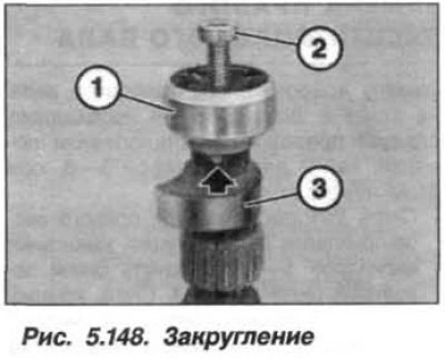
Install the magnetic wheel and fix its protrusion in the recess of the eccentric shaft. Insert the original (inv. No.07.11.9.903.466) antimagnetic bolt (2, M6) made of stainless steel and tighten it to a torque of 8.0 N·m (0.8 kgf·m).
Replace the liners (1, Fig. 5.149) needle bearing, and they must be installed so that their ends are located relative to each other, as shown in the figure.
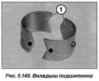
Insert the bearing shells into the support bridges so that they are fixed in the hole.
Lubricate the lower bearing shells with engine oil. Insert the eccentric shaft as shown in Fig. 5.150.
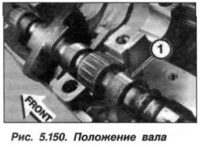
Lubricate the upper bearing shells with engine oil and install them on the bearing. The bearing shells should lock with an audible click. Check the position of the bearing shells. Install the left intake camshaft and assemble the engine.