
Remove the motor for adjusting the right eccentric shaft, the ignition coils of cylinders 1-4. Remove right cylinder head cover and unscrew spark plugs for cylinders 1-4. Remove right intake and exhaust VANOS control units.
Attention! First you need to rotate the intake camshaft so that when the support jumper is removed, the intermediate levers do not slip off and damage the camshaft.
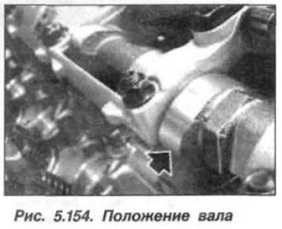
Turn the intake camshaft in the direction of rotation so that the inscription (1, fig. 5.154) was turned upwards in the direction of the axis of the 1st cylinder, and its cam (arrow) took up a horizontal position.
Attention! The bearing caps for the camshafts of cylinders 1-4 and 5-8 must not be interchanged.
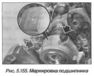
The inlet camshaft bearing caps on cylinder bank 1-4 are marked «LE1–LE5», read from the intake side. The pusher arms are easy to move when installing the support bridge. Do not turn over the support bar.
When assembling, install the bearing cover «LE1» so that the marking (pic. 5.155) read from the intake side. Set nuts (M7) and tighten them to 14 Nm (1.4 kgf·m).
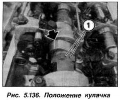
Turn the intake camshaft in the direction of rotation so that the cam of the 1st cylinder is in an inclined downward position (arrow), as shown in Figure 5.136. Marking (1) on the hexagon of the intake camshaft is located on top.
Install the right intake and exhaust VANOS control units, screw in the spark plugs for cylinders 1-4, install the cover for the right cylinder head and the ignition coils for cylinders 1-4.
Install the right eccentric shaft drive adjustment motor and assemble the motor.