
Table of contents: Car models "518", "520" ↓ Models "525" and "528" ↓
- Home
- BMW 5 Series
- E12
- Power unit
- Engine repair
- Removal the cylinder head
Removal the cylinder head (BMW 5 Series E12)
Note: This and subsequent sections provide recommendations for repair and maintenance of BMW vehicles "518", "520" and "520" with a 4-cylinder engine, "525" and "528", as well as features of repair and maintenance of the BMW "520" and "520i" engine with a 6-cylinder engine, "525i", "528i" and "535i", with the exception of which checks, adjustments and repairs are carried out in the same way as for the above models.
The cylinder head is removed on a cold engine.
Drain the cooling system. If the system is filled with antifreeze, drain it into a container for future use.
Car models "518", "520"
Disconnect the crankcase ventilation hose from the cylinder head cover.
Remove the air filter assembly (on the 518 model the filter is mounted on the vertical carburetor; on the "520" model, the filter is installed on the side of the horizontal carburetors; on models with a fuel injection engine, the filter is connected by a horizontal hose).
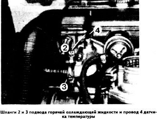
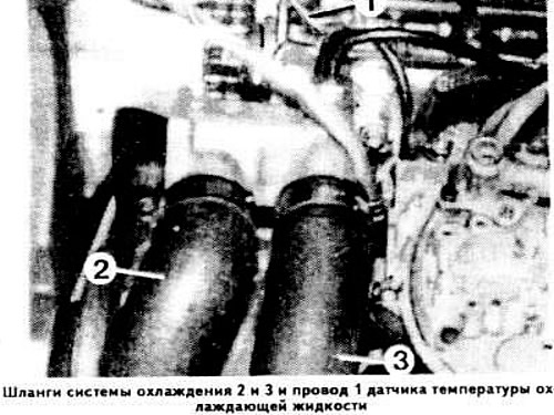
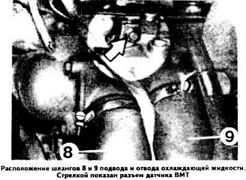
Disconnect two hoses 2 and 3 (see photo) supplying hot coolant, disconnect wire 4 from the coolant temperature gauge sensor.
Loosen the bolts securing the oil dipstick bracket and its tube.
Disconnect the fuel supply hose from the fuel pump.
Disconnect the power wire from the starter and remove it from the mounting eye.
Disconnect the throttle control rod from the carburetor.
Disconnect the intake manifold heating hose and remove the electrical wire bundle from the mounting brackets under the manifold.
Notes: On a fuel-injected engine, unscrew the fuel lines from the fuel pump housing and move them to the side. Disconnect the hose from the fitting on the distribution flange, disconnect the electrical wire from the temperature sensor.
Disconnect the vacuum hose and coolant hoses from the intake manifold.
Disconnect the wire from the oil pressure sensor and the low voltage wire from the ignition distributor. Remove the wires from the holders on the cylinder head.
Disconnect the power wires from the carburetor electric starter and from the solenoid shut-off valve, and route the wires downward.
Disconnect the exhaust pipe from the exhaust manifold.
Remove the cylinder head cover and the upper timing cover.
Remove the distributor cap and disconnect the spark plug wires.
Install the piston of the 1st cylinder (counting from the drive side of the valve timing mechanism) and TDC, aligning the ignition distributor rotor with the mark on its body, and the mark on the lower cover of the timing mechanism drive with the second mark on the crankshaft pulley.
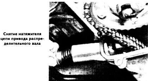
Remove the chain tensioner plunger, holding the spring, which is compressed with considerable force, from falling out.
Unlock and unscrew the camshaft drive sprocket mounting bolts.
Remove the camshaft drive sprocket together with the chain by moving it forward.
Gradually loosen the cylinder head fasteners in the reverse order of tightening, remove the cylinder head.
Models "525" and "528"
Remove the air cleaner assembly and cylinder head cover.
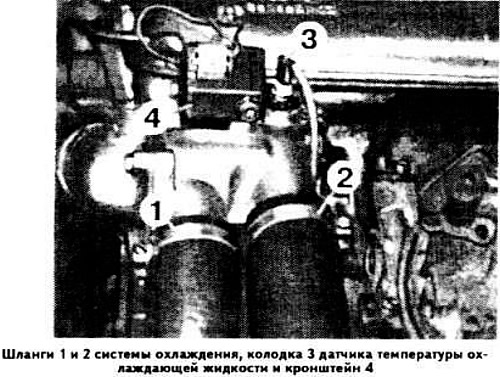
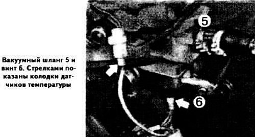
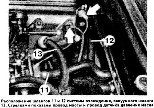
Disconnect hoses 1 and 2 (see photo), disconnect wire 3 from the coolant temperature gauge sensor, remove bracket 4.
Disconnect vacuum hose 5 from the intake manifold, disconnect the power wires from the carburetor electric starter and from the temperature sensor. Loosen screw 6 a few turns.
Disconnect the fuel supply hose from the fuel pump, disconnect the throttle control rod and the carburetor starter power supply wire bundle.
Disconnect the intake manifold heating hoses. Disconnect the wire from the oil pressure sensor. Disconnect the coolant supply and outlet hoses from the cylinder head and from the carburetor starter cover.
Remove the upper timing cover and chain tensioner plunger while holding the spring in place.
Unlock and remove the camshaft drive sprocket mounting bolts.
Remove the camshaft drive sprocket and chain by moving towards the front of the engine.
Disconnect the exhaust pipe from the exhaust manifold.
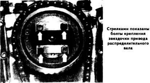
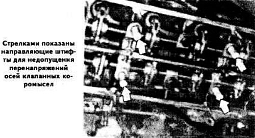
Gradually loosen the cylinder head mounting bolts in the reverse order of tightening. Install the guide pins (shown by arrows in the photo) in order to prevent movement or stress on the valve rocker arm axes.
Remove the cylinder head, head gasket, clean the mating surface of the cylinder head, plugging the threaded holes.
Since model year 1978 on BMW "525", "528" and "528i" removal of the cylinder head must be carried out taking into account the following:
Engines with Zenith 32/40 and 35/40 INAT carburetors with auxiliary starting device
Disconnect the wire from the negative terminal of the battery and the wires from the clamping coil.
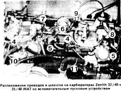
Disconnect wire 1 (see photo) from the coolant temperature gauge sensor.
Disconnect hoses 2 and 3 of the cooling system.
Disconnect wires 4 from the electromagnetic shut-off valves, disconnect plug connector 5 of the starting devices, connector 6 of the thermal time relay, disconnect ground wire 7 and the wire from the oil pressure sensor.
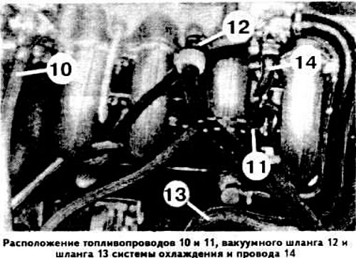
Disconnect fuel supply hose 9 from the fuel pump, coolant supply hose 10 to the auxiliary starting device and vacuum hose 11 from the check valve.
Disconnect coolant inlet and outlet hoses 12 and 13 from the intake manifold and cylinder head.
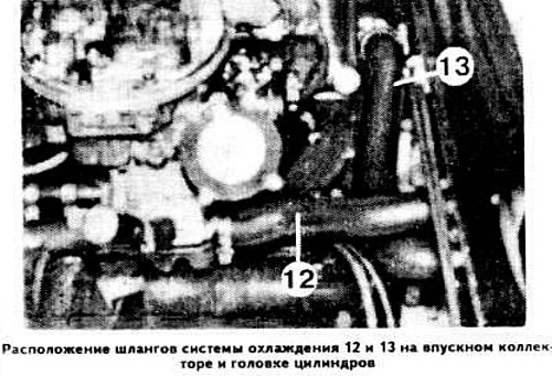
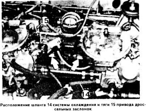
Disconnect the cooling system hose 14 from the intake manifold, disconnect the throttle control rod 15.
Remove the wiring harness from the mounting brackets.
Remove the oil dipstick bracket mounting bolt.
Engines with Solex 4A1 carburetor
Disconnect the wire from the coolant temperature sensor and disconnect the TDC sensor connector.
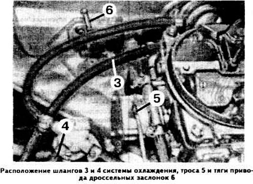
Disconnect fuel hoses 3 and 4, cable 5 and disconnect throttle control rod 6 at the top and bottom.
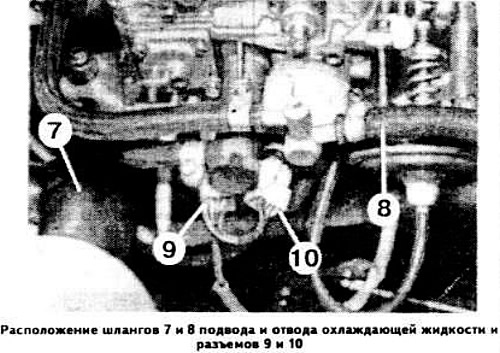
Disconnect cooling system hoses 7 and 8 and disconnect connectors 9 and 10.
Disconnect hoses 11 and 12 of the cooling system, vacuum hose 13, ground wire and wire from the oil pressure sensor.
Disconnect the electrical wires from the temperature sensor and remove the wire bundle from the holders. Fuel Injected Engines.
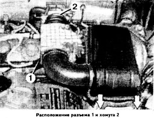
Disconnect the wire from the negative terminal of the battery, disconnect connector 1, remove clamp 2.
Remove the cylinder head cover.
Disconnect the spark plug wire ends and remove the distributor cap.
Disconnect the pads from the injectors.
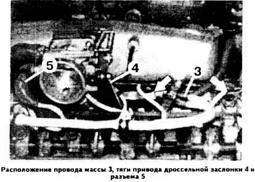
Disconnect the wire from the coolant temperature sensor and the ground wire 3.
Disconnect the throttle control rod 4 at the top and bottom.
Disconnect the throttle switch connector 5.
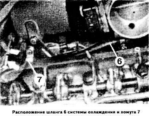
Disconnect hose 6 of the cooling system and remove clamp 7.
Disconnect the wires from the oil pressure sensor.
Disconnect hoses 8 and 9 of the cooling system, disconnect the TDC sensor connector.
Disconnect the fuel supply hose 10 and the fuel outlet hose 11, as well as the vacuum hose 12 and the hose 13 of the cooling system.
Disconnect wire 14.
Disconnect the outlet and inlet hoses of the interior heating system.
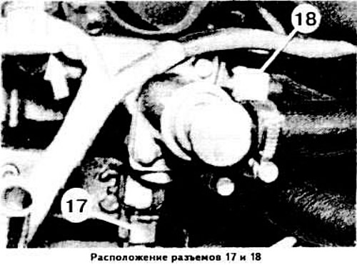
Disconnect wires 17 and 18 and pull the wire bundle up through the intake manifold opening.
Remove the bundle of wires from the holders (see arrow in photo).
Disconnect the intake manifold from cylinder 6.
Disconnect the exhaust pipes from the exhaust manifolds and from the gearbox mounting clamp.
Remove the air filter.
Drain the coolant.
Loosen the fan shroud mounting bolts and hang it above the fan.
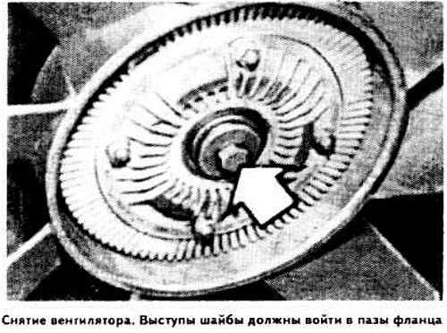
Loosen the fan mounting bolts and remove it upwards together with the casing.
Disconnect the hoses and electrical wires.
Disconnect the fuel supply and drain lines, electrical wires and vacuum hoses from the carburetor.
Disconnect the throttle control rod.
Disconnect the coolant supply and return hoses from the carburetor.
Disconnect the brake booster vacuum hose and the interior heater hose.
Disconnect the high-voltage wires from the distributor cap and remove the cap.
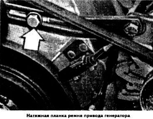
Remove the generator drive belt tensioner bolt.
Remove the alternator drive V-belt.
Remove the front bolt 12 (see photo) securing the generator bracket.
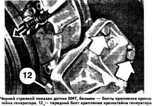
Remove the generator bracket.
Remove the TDC sensor from the holder.
Remove the spark plugs from the cylinder head sockets.
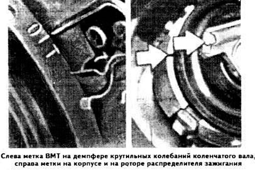
Set the piston of the 1st cylinder to the TDC position, while the rotor of the ignition distributor should coincide with the mark on the distributor housing.
Remove the camshaft drive belt cover by lifting it up.
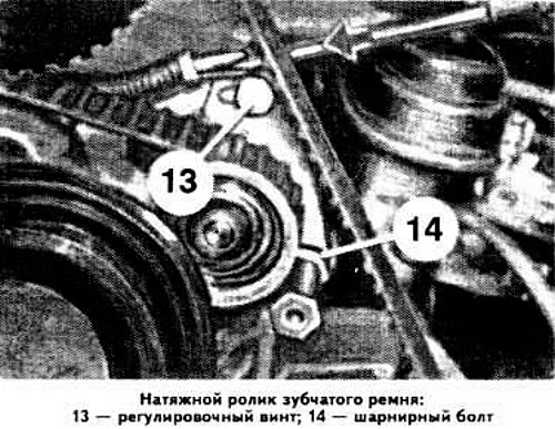
Loosen the tension roller mounting bolts, move the tension roller toward the engine and secure it in this position.
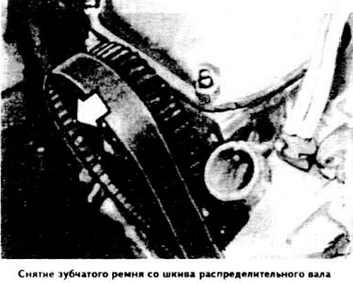
Remove the timing belt from the camshaft pulley. After this, do not turn the engine crankshaft.
If the timing belt is to be used again, mark it with the direction of rotation.
Remove the cylinder head cover, remove the spring washers.
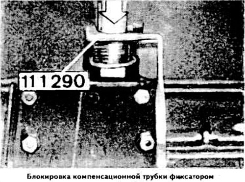
Move the compensation tube downwards and secure it with tool 111290.
Remove the cylinder head.
This article is available at russian, bulgarian, belarusian, ukrainian, serbian, croatian, romanian, polish, slovak, hungarian
Article verified: Polikarpov Saveliy
Share information:
Previous articles
БМВ E12: Engine repair
Next articles
Similar articles on other types of BMW cars:
Removal the cylinder head BMW 3 Series E21 (1975-1983)
Removal and installation the cylinder head BMW 3 Series E30 (1982-1994)
Cylinder head of gasoline engines of the M52 series — removal and… BMW 7 Series E32 (1986-1994)
Removal and installation cylinder head covers BMW 7 Series E38 (1994-2001)
Removal and installation the cylinder head BMW X3 E83 (2003-2010)
Cylinder head — design description BMW X5 E53 (1999-2006)
Link in different formats to this page
Visitor comments
No comments yet
- General information
- Governing bodies
- Manual
- Maintenance
- Power unit
- Engine repair
- Lubrication system
- Cooling system
- Ignition system
- Supply system
- Injection system (gasoline)
- Injection system (diesel)
- Exhaust system
- Transmission
- Clutch
- Car gearbox
- Front axle
- Rear axle
- Chassis
- Steering
- Brake system
- Wheels and tires
- Body
- Interior
- Exterior
- Heating system
- Electrical equipment
- Equipment and devices
- Power devices
- Windscreen wipers
- Electrical circuits
- General information
- Manual
- Maintenance
- Power unit
- Engine repair
- Ignition system
- Engine lubrication system
- Cooling system
- Fuel system (gasoline)
- Fuel system (diesel)
- Exhaust system
- Transmission
- Clutch
- Car gearbox
- Chassis
- Front and rear suspension
- Steering
- Brake system
- Body
- Exterior
- Interior
- Electrical equipment
- Heating system
- Equipment and devices
- Power devices
- Electrical circuits
- General information
- Manual
- Maintenance
- Power unit
- Engine in a car
- Engine overhaul
- Cooling system
- Supply system
- Ignition system
- Control system
- Transmission
- Clutch
- Manual gearbox
- Automatic gearbox
- Transmission line
- Chassis
- Steering
- Front suspension
- Rear suspension
- Brake system
- Body
- Body elements
- Car care and painting
- Electrical equipment
- Heater and air conditioner
- Equipment and devices
- Starter and generator
- Electrical circuits
- General information
- Operation and maintenance
- Specifications
- Power unit
- Engine repair
- Cooling and lubrication system
- Supply system
- Ecotronic power supply system
- Fuel injection system
- Ignition system
- Transmission
- Clutch
- Gearbox BMW 242/4
- Gearbox Getrag 262/8
- Gearbox Getrag 265/6
- Automatic gearbox
- Cardan gear
- Rear axle
- Chassis
- Steering
- Front suspension
- Rear suspension
- Brake system
- Electrical equipment
- Equipment and devices
- Electrical circuits