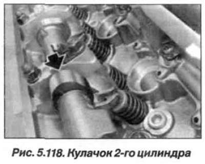
Turn the exhaust camshaft by the hexagon so that the cam of the 2nd cylinder (arrow, Fig. 5.118) stood with his nose up.
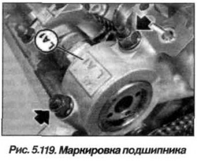
The inlet camshaft bearing caps on cylinder bank 1–4 are marked "LE1–LE5" as read from the inlet side.
Turn the exhaust camshaft so that the cam of the 2nd cylinder is facing up.
Install the bearing cap "LA1" so that its marking (fig. 5.119) was read from the intake side.
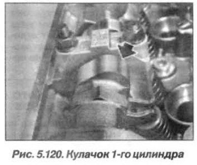
Before installing the VANOS actuators, turn the exhaust camshaft counter-clockwise so that the cams of cylinder 1 are tilted upwards (arrow, Fig. 5.120).