
Note: The technology for removing and installing the intake camshaft has some differences.
Removing the intake camshaft.
Prepare the equipment "11.9.470", "11.9.472", "11.9.473", "11.9.474", "11.9.475", "11.9.480" and "11.9.490" and "cash register" for the layout of the removed parts by cylinder numbers (5–8).
Remove the left eccentric shaft adjustment motor, the ignition coils of cylinders 5–8, the left cylinder head cover, unscrew the spark plugs from cylinders 5–8 and remove the left VANOS actuators.
Attention! Very important! First, it is necessary to turn the intake camshaft so that when removing the support bridge, the intermediate levers do not slip and damage the camshaft.
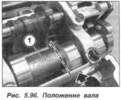
Turn the intake camshaft counterclockwise so that the inscription (1, Fig. 5.96) was directed upward in the direction of the axis of the 8th cylinder, and its cam (arrow) took a horizontal position.
Caution! The bearing caps of the camshafts of cylinders 1–4 and 5–8 cannot be interchanged.
The inlet camshaft bearing caps on cylinder bank 5–8 are marked "RE1–RE5" as read from the inlet side and must not be interchanged.
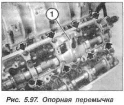
Loosen the fastening nuts and remove the bearing cover "RE1". Loosen and unscrew the eight nuts (arrows, Fig. 5.97) fastening the support crossbar (1), starting from the outer nuts and moving towards the center.
Caution! When removing the support crossbar, do not turn it over.
Pusher levers (1, Fig. 4.97) divided into classes according to tolerances.
On the intake side, only tappet levers of one tolerance class can be installed per cylinder. Tolerance classes are designated by numbers from 1 to 4 (see arrow).
Used push rods must only be installed in the same locations.
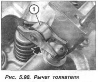
After removing the support bridge, the roller levers of the pushrods become accessible. Levers (1, Fig. 5.98) do not remove the tappets from the intake side.
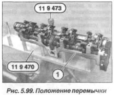
Clamp the device "11.9.470" in a vice and carefully remove the support bridge from the cylinder head by moving it upwards. Do not turn the support bridge over. Place the support bridge (1) together with the intake camshaft and eccentric shaft, as shown in Figure 5.99, on the device "11.9.470". Secure the support bridge with the special nut - device "11.9.473".
Attention! The lower part of the support bridge is machined together with the cylinder head and therefore cannot be repositioned, it remains on the cylinder head.
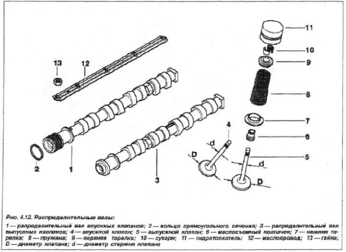
If after removing the intake camshaft you also need to remove the eccentric shaft, you need to unscrew the bolts (11, see Fig. 4.12) and remove the eccentric shaft position sensor (10).
Note: Removal of the intermediate levers should begin with the 8th cylinder, and proceed similarly for cylinders 5–7.
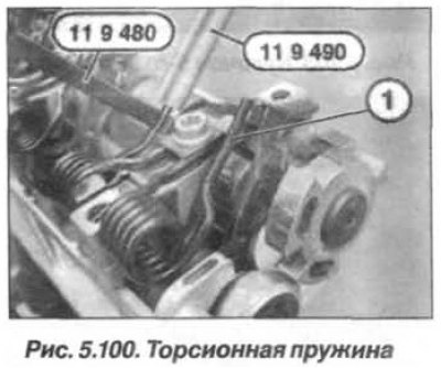
Raise one end of the torsion spring using the device "11.9.480" and hold it in this position. Remove the intermediate lever by moving it upwards and place it in order in the "cashbox". Continuing to hold the torsion spring, install the protective device "11.9.490" (fig. 5.100) onto the end of the torsion spring. Rest the protected end of the torsion spring on the intake camshaft.
Attention! Intermediate levers (22, see Fig. 4.12) are divided into tolerance classes, which are designated by numbers from 1 to 5. Within one cylinder head, they can only be installed of one tolerance class.
Intermediate levers that have been in use should only be installed in the same locations.
The bearing caps of the camshafts of cylinders 1–4 and 5–8 cannot be interchanged.
The intake camshaft for cylinders 5–8 is designated "EIN 58".
Raise the other end of the torsion spring using the "11.9.480" device and hold it in this position. Remove the intermediate lever by moving it upwards and place it in order in the "cashbox". Continuing to hold the torsion spring, install the "11.9.490" protective device on its other end. Rest the protected end of the torsion spring on the intake camshaft.
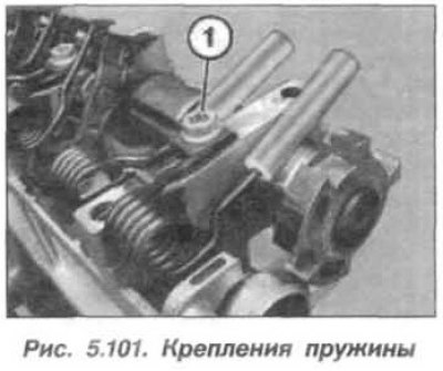
Remove the screw (1, Fig. 5.101) fastenings of the torsion spring (2) and remove it together with the device "11.9.490".
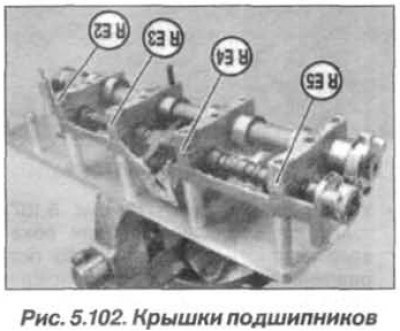
Note. Intermediate levers and torsion springs of cylinders 5–7 are removed in the same way and laid out in order. Bearing caps are designated – "RE2" – "RE5".
Unscrew the special nut - device "11.9.473" and remove the bearing caps "RE2" – "RE5" (fig. 5.102), put them in order in the "cash register".
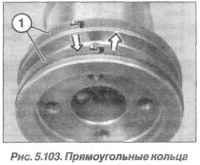
Hook and remove the intake camshaft, inspect it, and replace the rectangular rings if necessary (1, Fig. 5.103), because they break easily. The rings snap into place at the joint. To remove the ring, you need to press it in from one side (left arrow) into the groove, and on the other side pull it up (right arrow) and release the lock. Carefully spread the ring and remove it by moving it forward.
Replace the wheel if necessary (8, see Fig. 4.12) camshaft position sensor, for which unscrew the bolt (9) and remove the wheel.