
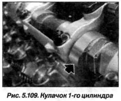
Turn the exhaust camshaft by the hexagon so that the cam of the 1st cylinder (arrow, Fig. 5.109) stood up horizontally.
The inlet camshaft bearing caps on cylinder bank 1–4 are marked "LE1–LE5" as read from the inlet side.
Removal of intermediate levers should begin with the 4th cylinder; for cylinders 1–3, the actions are similar.
The intake camshaft 1–4 is designated "EIN 14".
Installation of the right intake camshaft on cylinder bank 1–4 must begin with cylinder 4.