
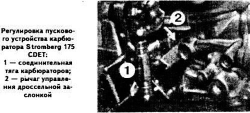
Adjustment of the automatic starter and fast idling
Starter adjustments should only be made with fully synchronized carburetors and a warm engine.
Remove the air filter.
Disconnect rod 1 (see photo), connecting the carburetors and move the throttle control lever 2 down about 15 mm.
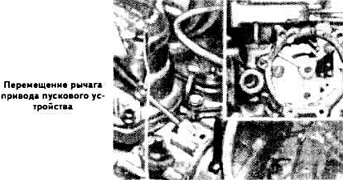
Insert a screwdriver into the hole in the starter housing and slide the starter drive arm clockwise. Release the throttle control lever and release the starter drive lever. As a result, the throttle control lever, which has two profiles, should take the 1st or 2nd detent position. Measure clearance «A» (see photo) between the throttle control lever and the stop adjusting screw. It should be equal to:
- 4.5-5 mm when using an ignition distributor without a vacuum regulator;
- 3.9±0.1 mm with vacuum hose disconnected;
- 2.4±0.1 mm with vacuum hose connected.
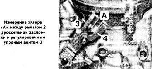
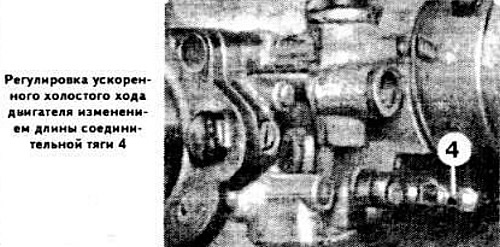
By changing the length of the connecting rod 4 (see photo), set the engine speed to fast idle (while the throttle control lever must be in the 2nd fixed position) during operation of each carburetor 1700±100 rpm. After adjustment, the mode of accelerated idling of the engine during the operation of both carburetors should be in the range of 2000-2200 rpm.
Note. On the carburetor removed from the car, the starting gap of the throttle valve should be 0.4 mm (when connecting carburetors with right-hand and left-hand threads) or 7 mm (when connecting carburetors through traction and backstage).
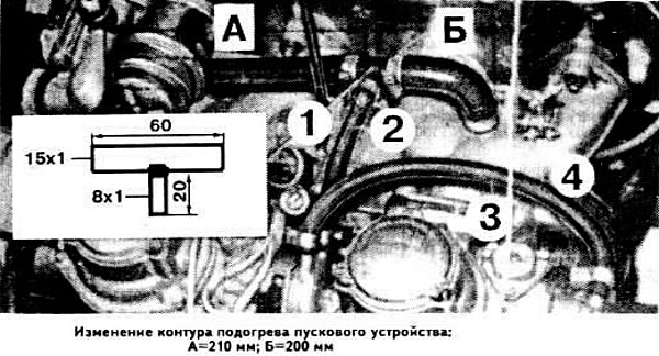
If, after stopping a warm engine, the automatic starter turns on again to start, change the circuit of its heating of the starting device, as shown in the photo. For this:
- drain the liquid from the cooling system.
- Disconnect starter heater hose from intake manifold. Unscrew the threaded fitting and plug the hole with a M 10x12 mm screw, placing an aluminum washer under its head;
- loosen both covers of the starter housing and turn them so that the coolant inlet and outlet hoses are directed as shown in the photo;
- cut the top hose so that the distance «A» was equal to 210 mm, and «B» - 200 mm, and connect its segments with a tee 1 made from improvised materials;
- connect hose 2 to the free end of the tee and connect hoses 3 and 4.
Engine idle adjustment
Remove the air filter. Connect the BMW monitoring device and the gas analyzer.
Disconnect the throttle control link and connect the service link 6083/1 (6083 on vehicles with automatic transmission).
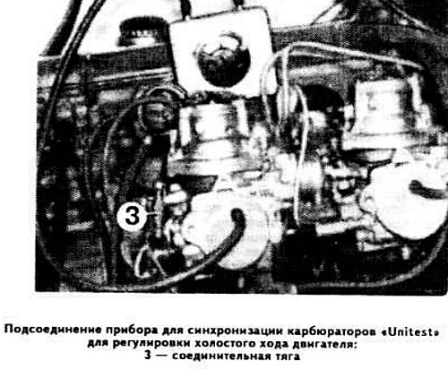
Remove the intake chamber and connect the carburetor timing device «Unitest», as shown in the photo.
Start the engine and bring the engine speed to approx. 2000 rpm by adjusting the length of the rod 6083/1.
Then adjust the length of the connecting rod 3 (see photo) so as to achieve a stable position of the pointer of the control device at zero on the scale. Remove service rod 6083/1.
Connect the throttle control rod. The crankshaft speed should not change. Otherwise, adjust the length of the throttle linkage so that the bottom stop of the intermediate lever rests on the engine mount and the throttle levers rest on the stop screws (it is forbidden to change the position of the stop screws, locked with paint).
Install the air filter and start the engine.
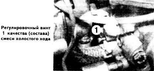
With adjusting screw 1 quality (composition) rear carb mixture adjust carbon monoxide content (SO) in the exhaust gases so that it is equal to 2.5-3.5% at a crankshaft speed of 900-1000 rpm.
Using the adjusting screw 2 for the amount of the mixture, set the idle speed in the range of 900-1000 rpm. By turning adjusting screws 1 and 2 alternately, achieve the specified values of the engine idle mode and CO content.
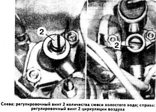
If it is not possible to set the idle speed of 900-1000 rpm, then only in this case remove the suction chamber and disconnect the drive rod. Connect the carburetor timing device «Unitest» and turn out the adjusting screw 2 of the air circulation until the engine idle mode is stabilized. Use the stop screws to synchronize the operation of the carburetors at a crankshaft speed of 1000 rpm. Connect the drive rod and adjust the engine idle and CO content as above.
Setting the fuel level in the float chamber
Remove the carburetor from the engine.
Warning. Position the carburetor with the throttle side flange down. Do not move the throttle and piston as this will cause oil to leak from the piston damper. In case of accidental movement of the throttle valve or piston, proceed as indicated in subsection «Checking the oil level».
Remove float chamber 44 (see picture), axle floats and floats. Check their condition, then replace the floats and the axis of the floats.
Place the carburetor body in a vertical position and measure the distance «A» (see photo) between the point at the top of the float and the plane of contact of the float chamber, which should be equal to 17±0.5 mm. In this case, the lever should rest on the needle without sinking the ball.
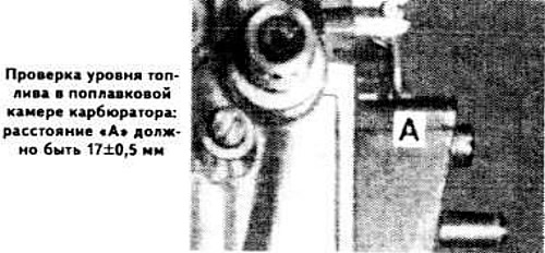
If necessary, achieve the correct size by bending the float arm.
Replace the float chamber and install the carburetor.
Suction chamber replacement
Remove the air filter and suction chamber by removing the three screws.
Install a new suction chamber and air filter.
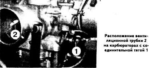
Note. After installing connecting rod 1 (see photo) a ventilation tube 2 is installed on the suction chamber, the absence of which leads to a significant loss of engine power.
Checking the oil level
Remove protective cover 67 (see picture) and check the condition of the gasket. The oil level must reach the bottom edge of the piston cover. Do not reuse drained carburetor oil.
Remove piston damper (see below).
Fill with 20cm3 type automatic transmission oil «Automatic Transmission Fluid» into the piston cover, of which 6 cm - into the sleeve, which corresponds to an oil level of approximately 40 mm.
When installing the removed parts, make sure that the piston damper tube ventilation holes are not clogged.
Removing the piston damper
Remove protective cover 67 (see picture), lift the capillary tube bracket and remove the tube, noting its position.
Unscrew and remove the piston damper.
When installing the shock absorber, orient the capillary tube in accordance with the mark made earlier, the end of which should be at the lowest point of the piston cover 59 (see picture).
Fill the shock absorber with oil.
Piston Diaphragm Replacement
Carry out the above operations, then remove the piston cover 59, holding it as it is lifted by the spring 58. Let the oil drain (do not use drained oil).
Remove the piston with the diaphragm by gradually lifting the outer edge of the diaphragm.
Remove the washer 54 holding the diaphragm to the piston and remove the diaphragm.
When assembling, make sure that the protrusion of the diaphragm enters the groove of the carburetor body.
Fill the piston cap with oil (see above).
Replacing the jet needle
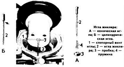
Carry out the above operations, then remove the lock screw 57 and the needle 56. The jet needle can be conical or cylindrical.
When installing the conical needle, direct the spring 4 as shown in the photo and insert the plug 3 so that it is in line with the piston.
When installing a cylindrical needle, insert the needle so that the upper edge of the hole, shown by the arrow in the photo, is at the level of the piston bottom.