
Removal
Remove the rear wheel.
Disconnect the drive shaft from the hub flange and tie it to the body. At the same time, tighten the handbrake.
Remove the handbrake cable from the lever.
Pump out the brake fluid from the expansion tank.
Pull the pulse sensor connector downwards and disconnect.
Remove the rear seat and disconnect the pulse sensor connector.
Remove the handbrake cable from the guide and disconnect the brake line.
Unscrew the tilt sensor support rod from the fork.
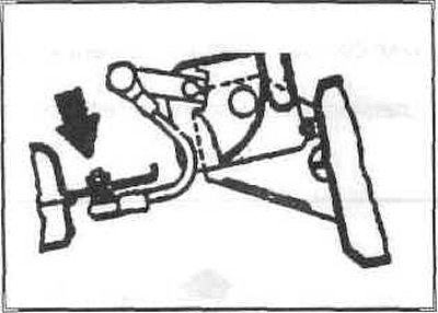
Support the trailing arm.
Unscrew the trailing arm from the cross beam. Remove the stabilizer.
Disconnect the shock absorber from the trailing arm. Remove the trailing arm.
Installation
Installation is carried out in the reverse order of removal
Tighten the mounting bolts completely with the vehicle in its normal position.
When installing the trailing arm, first insert the inner silent block bolts.
The tilt sensor is installed as follows:
Turn on the ignition, set the normal ride height. Measure and adjust to the correct position. Loosen the switch mounting bolt (1). Center the hole (2) with a 4 mm drill.
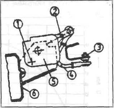
Retighten the mounting bolt.
Trailing arm silent block - replacement
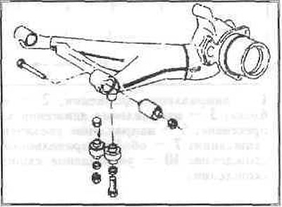
Remove the trailing arm.
Press out the silent blocks using tool (A).
Cover the silent blocks with special oil and press them in with a tool
Note: The longer part of the rubber bushing points towards the center of the vehicle.
If necessary, the rear wheel alignment can be adjusted by installing eccentric rubber bushings.
Example
Measure the rear suspension with an optical instrument.
Set the values: There is +2.5 mm on the left back. Should be +2.0 mm. Correction value -0.5 mm.
Remove the trailing arm and outer bushing.
Remove the trailing arm sleeve horizontally.
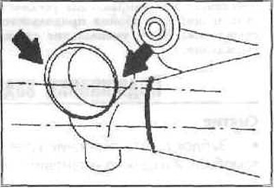
Determine the angle of rotation from the diagram.
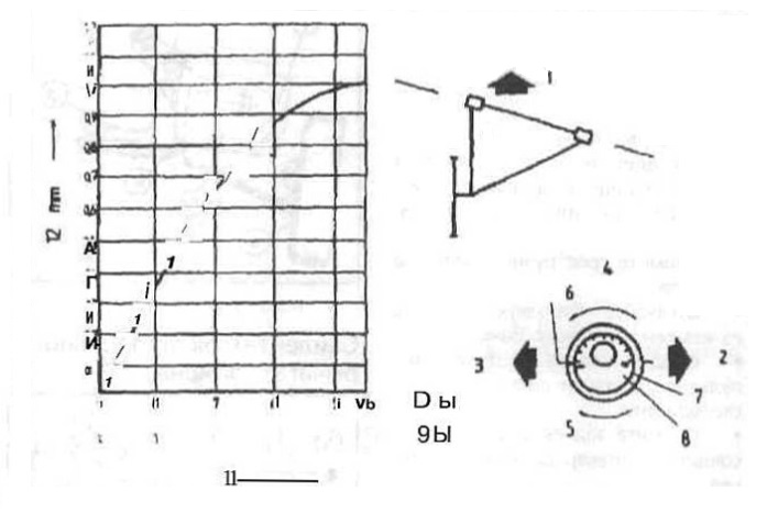
Left wheel
1 - direction of movement;
2 — direction of movement of the inner silent block;
3 — direction of movement of the outer silent block;
4 - pressing instructions;
5 - direction of increasing convergence;
6 - direction of decreasing convergence;
7 — longitudinal arm sleeve;
8 — silent block;
9 - increase convergence;
10 - decrease in convergence;
11 — rotation angle;
12 - change in convergence.
Align the corresponding values marked on the edge of the bushing on the rubber bearing.
Coat the rubber bearing with special oil and press it in, aligning the marks.
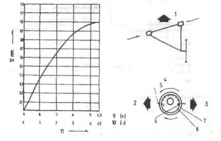
Right wheel
1 - direction of movement;
2 — direction of movement of the inner silent block;
3 — direction of movement of the outer silent block;
4 - pressing instructions;
5 - direction of increasing convergence;
6 - direction of decreasing convergence;
7 — longitudinal arm sleeve;
8 — silent block;
9 - increase convergence;
10 - decrease in convergence;
11 — rotation angle;
12 - change in convergence.