
Table of contents: Models with M57 engine ↓ Models with M57 engine ↓
- Home
- BMW 7 Series
- E38
- Power unit
- Fuel system (diesel)
- Removal and installation of fuel lines and fuel distribution line
Removal and installation of fuel lines and fuel distribution line (BMW 7 Series E38)
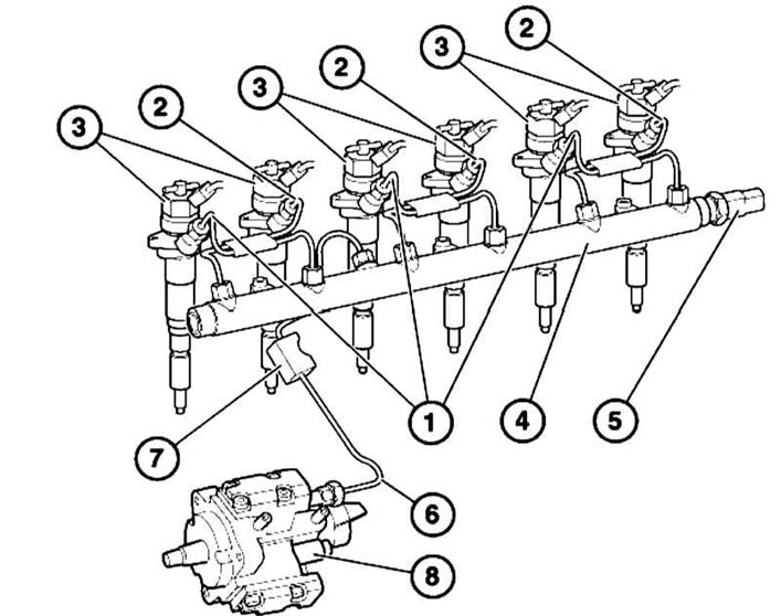
M57 Engine Fuel Rail Components
1 — Pressure pipeline to cylinders No.1, 3 and 5
2 — Pressure pipeline to cylinders No.2, 4 and 6
3 — Injectors
4 — Fuel distribution line
5 — Pressure sensor
6 — High-pressure fuel pump pipeline
7 — Rubber-metal hinge
8 - Fuel injection pump
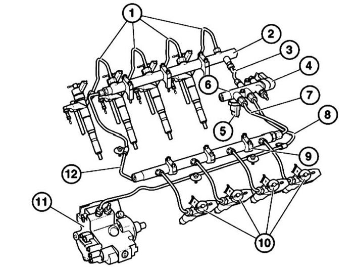
1 - Pressure pipelines between the distribution main and the injectors
2 — Fuel distribution line
3 — Pressure line between the right fuel distribution line and the fuel distributor
4 — Pressure regulator
5 — Pressure sensor
6 — Fuel distributor
7 — Pressure line between the left fuel distribution line and the fuel distributor
8 — Pressure pipeline between the high-pressure fuel pump and the fuel distributor
9 — Mounting bracket
10 — Injectors
11 — Fuel injection pump
12 - Pressure pipe between both right fuel distribution lines
Models with M57 engine
1. Remove all pressure pipes, having first closed the generator to prevent any working fluids from getting on it.
2. Disconnect the pressure sensor connector (see illustration).
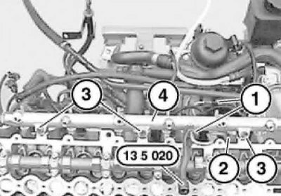
3. Using tool No.13 5 020, loosen the union nuts (1) on the fuel distribution line and loosen the union nuts on the high-pressure fuel pump. Disconnect the pressure pipe from the fuel distribution line. Unscrew the bolts (3) and remove the fuel distribution line (4).
4. Installation is carried out in the reverse order. Pay attention to the correct installation of the rubber-metal hinge (2).
Models with M57 engine
The removal of the left distribution line is described below; the right one is removed in the same way.
1. Remove the pressure pipes between the fuel distribution line and the injectors.
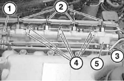
2. Loosen the union nuts (1, 2 and 3) of the pressure pipes and unscrew the bolts (4) on the bracket. Remove the fuel distribution line (5).
3. Installation is carried out in the reverse order. Please note the different lengths of the bolts.
This article is available at russian, bulgarian, belarusian, ukrainian, serbian, croatian, romanian, polish, slovak, hungarian
Article verified: Polikarpov Saveliy
Share information:
Previous articles
БМВ E38: Fuel system (diesel)
Next articles
Similar articles on other types of BMW cars:
Mechanical fuel pump — checking, adjustment, removal and installation BMW 3 Series E21 (1975-1983)
Fuel system expansion tank — removal and installation BMW 3 Series E46 (1998-2006, petrol)
Removal and installation the fuel pump BMW 5 Series E34 (1988-1996)
Removal and installation the fuel level sensor / fuel pump BMW 5 Series E39 (1995-2003)
Removal and installation the fuel filler cap BMW X3 E83 (2003-2010)
Removal the fuel tank BMW X5 E53 (1999-2006)
Link in different formats to this page
Visitor comments
No comments yet
- General information
- Introduction to guide
- Manual
- Maintenance
- Power unit
- Engine M60/1, M60/2 (petrol)
- M62 engine (petrol)
- M57 engine (diesel)
- M67 engine (diesel)
- Cooling system
- Fuel system (petrol)
- Fuel system (diesel)
- Exhaust system
- Ignition and control systems
- Charge and launch systems
- Transmission
- Clutch
- Mechanical gearbox
- Automatic gearbox
- Cardan and drive shafts
- Chassis
- Brake system
- Front suspension
- Rear suspension
- Steering
- Body
- Exterior
- Interior
- Electrical equipment
- Equipment and devices
- Lighting
- Heating and air conditioning
- Electrical circuits
- General information
- Care and maintenance
- Power unit
- Minor engine repair
- Engine overhaul
- Lubrication system
- Cooling system
- Ignition system
- Supply system
- Injection system (petrol)
- Injection system (diesel)
- Exhaust system
- Transmission
- Clutch
- Manual gearbox
- Automatic gearbox
- Cardan gear
- Rear axle and shafts
- Chassis
- Front suspension
- Rear suspension
- Steering
- Wheels and tires
- Brake system
- Body
- Body elements
- Electrical equipment
- Equipment and devices
- Electrical circuits