
Attention! After installing the fuel tank, before the first start of the engine, measure the electrical resistance between the ground flag (at the filler neck of the fuel boom) and the wheel hub. It should be approximately 0.6 Ohm.
Fill the fuel tank with at least 6-7 liters of fuel.
Avoid damaging the seals.
Removing the fuel tank is the same for all models of the X5/E53 series.
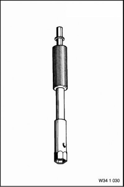
The fuel tank must be removed in the following order. Drain the fuel tank. Using the "34.1.030" tool, unscrew the lock nuts and adjusting sleeves from the parking brake drive cables.
Remove the rear seat and take out the rubber plugs from the protective mat. Unscrew the nuts securing the metal covers (left and right).
Disconnect the SS (1. Fig. 3.151) from the tank fill level sensor installed in the left tank.
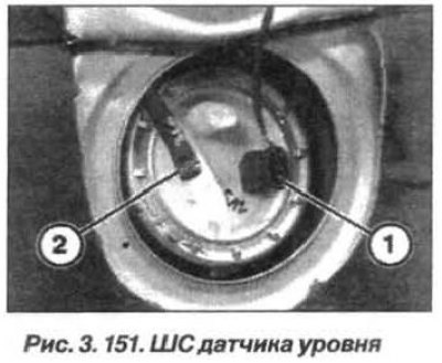
Disconnect the SS from the feeder block in the right tank. Loosen the clamp and disconnect the fuel tank ventilation line (see right tank).
Remove the propeller shaft assembly.
Remove the self-tapping screws on the left fuel tank guard panel. Remove the bolts on the left wheel arch guard. Bend the guard back and remove the bolt (1, Fig. 152).
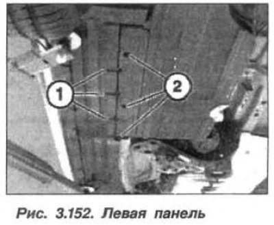
Remove the screws and nuts securing the panel. Remove the left panel by moving it downwards.
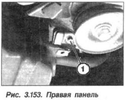
When removing the right protection panel, do the same, bending back the protective cover of the right wheel arch and unscrewing the bolt (1, Fig. 3.153).
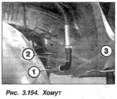
Release the parking brake cables from the clamps and disconnect them from the fuel tank. Remove the fuel filler by unscrewing the bolts and opening the clamps that secure it. Disconnect the ventilation pipe from the tank when refueling. Remove the rear, right wheel and its protective cover. Loosen the clamp (1, Fig. 3.154) and disconnect the hose (2) from the fuel tank (3). Replace the clamp.
Using thin cloth tape, mark the following pipes before and after the connection line (fig. 3.155):
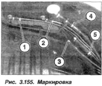
- 1. bypass (∅ 8 mm);
- 2. fuel tank ventilation (∅ 8 mm);
- 3. bypass (∅ 8 mm);
- 4. ventilation when filling (∅ 18 mm);
- 5. ventilation when filling (∅ 18 mm).
Open the pipe connection clamps so that the clamps do not have to be pulled through the hole in the wheel arch.
Support the fuel tank with a jack using a large wooden block, but so that the tension straps are free.
Remove the rear right bolt (14, see Fig. 3.20) straps (9) securing the fuel tank (1), unhook and remove the tension strap.
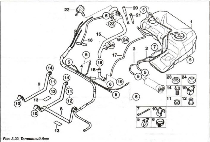
1 - fuel tank; 2 - supply pipeline; 3 - drain pipe; 4 - pipelines; 5, 19 - clamp; 6 - clamp; 7 - bandage; 8, 9 - tape; 10 - damper; 11,12 - bushing; 13 - overlay; 14 - bolt; 15 - filling pipeline; 16 - pipeline; 17, 20 - drain pipe; 18 - hose; 21 - nozzle; 22 - filler cap; 23, 24 - nut; 25 - fuel filter with pressure regulator
Unscrew the rear left bolt (14) and the middle bolt (8) of the fuel tank fastening strap (1), unhook and remove the clamp strap.
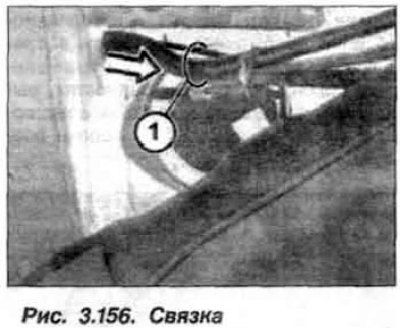
Carefully lower the fuel tank by 20 cm and remove the hose bundle from the wheel well (1, Fig. 3.156).
Carefully lower the fuel tank further and set it aside.
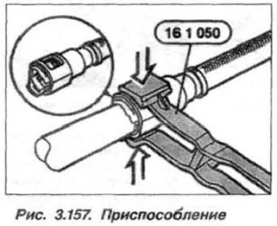
To disconnect the pipeline from the activated carbon tank, use the device "16.1.050" (1. Fig. 3.157).
The fuel tank should be installed in the reverse order, paying attention to the presence of the damper (10. see fig. 3.20) in both holds.
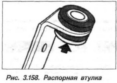
Pay attention to the rubber-metal hinges and spacer bushings in the holes of the tie straps for the fastening bolts. Wide belt (arrow, Fig. 3.158) on the expansion sleeve indicates the bolt head.
Tighten the bolts (M8) securing the tie straps to a torque of 20–23 N·m (2.0–2.3 kgf·m). Replace the fastening clamps and tighten to the torque of:
- ∅ 10—16 mm 2.0 N·m (0.2 kgf·m);
- ∅ 37–43 mm 4.0 N·m (0.4 kgf·m).
Adjust the parking brake drive.