
Attention! When carrying out work on fuel pipelines, ensure the collection of escaping fuel and its further disposal.
Removing the intake manifold (23, see fig. 3.18) must be done in the following order.
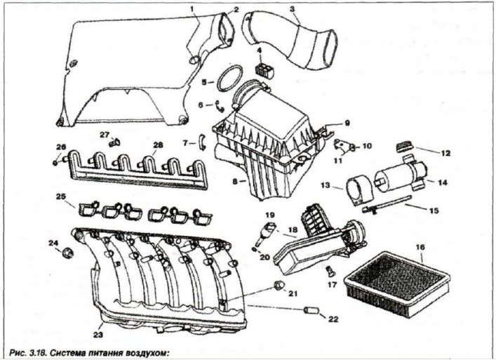
1 - rubber bushing; 2 - air intake; 3 - casing; 4 - shock absorber; 5 - ring (91x6); 6 - bracket (34 mm); 7 - snob (42 mm); 8 - noise silencer / housing; 9 - spacer sleeve; 10 - bracket; 11 - bolt (M6x12); 12 - bell; 13 - hinge; 14 - valve x.x; 15 - valve bracket; 16 - replaceable filter element; 17 - bolt T (M6x18); 16 - executive unit; 19 - temperature sensor; 20 - ring (8x3); 21 - nut (M6); 22 - bushing; 23 - intake manifold; 24 - nut (M7); 25 - gaskets; 26 - ring (7X3); 27 - screw; 28 - adapter
Disconnect «-» terminal AB. Remove the upper engine cover and intake (2) air flow.
Remove the upper casings that cover the engine nozzles and ignition coils, for which purpose remove the plugs and unscrew the bolts located under them, remove the cover from the oil fill pipe.
Disconnect the loops of the oxygen concentration sensors in the exhaust gases (DKK-OG). Unfasten the output clamp «+» wires on the intake manifold and disconnect the output «+» wires for connecting an additional power source. Press the latch and remove the crankcase ventilation hose.
Remove brace (1, fig. 3.144), disconnect the loop (2) intake air temperature sensor.
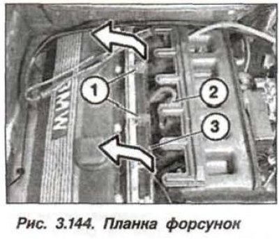
Remove mounting plate (3) injectors and set it aside. Disconnect the AL from the fuel tank vent valve and remove the valve from the holder on the intake manifold.
Release the fuel line from the holder on the manifold and undock it. Remove the dipstick for the oil level indicator and unscrew the fastening of the dipstick guide tube. Loosen the clamp and disconnect the oil return hose to the oil level gauge guide tube.
Remove throttle body. Disconnect the loops and move the cable box aside. Release the knock sensor loops from the holder. Loosen the nut (24, see fig. 3.18) intake manifold mounts.
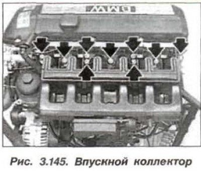
Loosen the fixing screws (9 pcs., arrows, fig. 3.145) intake manifold and remove it.
Close all intake manifold and cylinder head openings. The ingress of foreign bodies into the intake ducts can lead to engine failure.
The installation of the intake manifold should be carried out in the reverse order, while it is necessary to check the integrity of the gaskets (25, see, fig. 3.18) and make sure they are in the correct position. Replace if necessary.
Check the damping rubber mounting pads, if necessary, replace them together with the intake manifold support and install its support.
Install the intake manifold on the head of the block and evenly, crosswise tighten the bolts of its fastening to a torque of 20-25 N·m (2.0—2.5 kgf·m).