
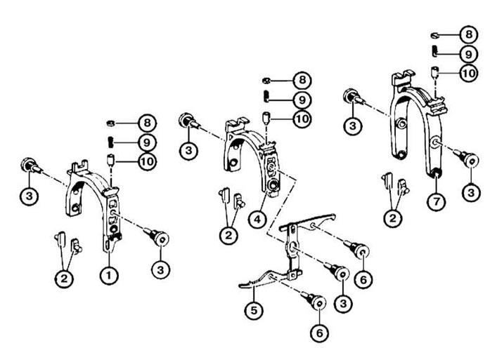
Components of the gearshift drive installation
1 — Fork of inclusion of V transfer and transfer of a backing
2 - Crackers
3 - Hinge pin
4 — Fork of inclusion of I and II transfers
5 - Locking lever
6 — Screw of fastening of the blocking lever
7 — Fork of inclusion of III and IV transfers
8 - Latch cover
9 - Lock spring
10 - Locking pin
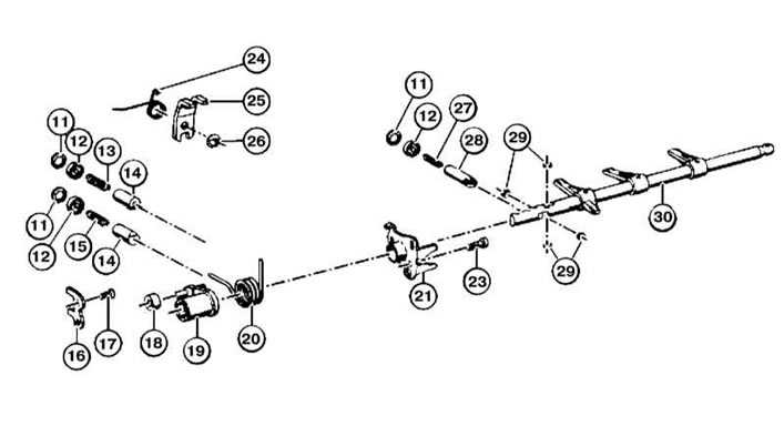
Components of the gearshift drive installation
11 - Retaining ring
12 - Latch cover
13, 15, 27 - Detent spring
14 - Retainer
16 - Thrust plate
17, 23 - Screw
18, 29 - Rollers
19 — the Lever of a choice of transfers
20, 24 - Spring
21 - Backstage
25 - Locking lever
26 - Stopper
28 - Lock pin
30 — a rod of a choice of transfers
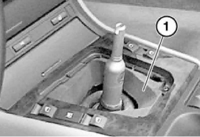
Gear lever
1. At the manual transmission GS6-37BZ/DZ (models with M57TU engine) first remove the exhaust system and its heat shield, see Chapter Power supply and exhaust systems.
2. With a strong jerk, remove the shift knob.
Do not turn the handle when removing, otherwise the angular displacement lock located in the button will be cut off. When installing, put the handle on the lever, align it and push it down until it clicks into place.
3. Lightly squeeze the frame of the shift lever boot and remove the boot from the center console.
4. Remove soundproofing.
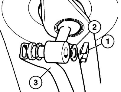
5. Remove the latch (1) and puck (2). Take out the traction (3) gear change drive.
At installation grease a finger of draft of a drive of a gear change.
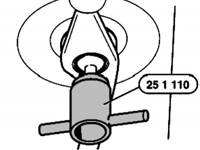
6. Insert tool no. 25 1 110 into the bearing and turn it 90°counterclockwise. Push up the bearing shells from the shift lever shaft.
7. Take a rubber boot from an opening of a body and take out it together with the gear change lever in an upward direction.
8. Installation is carried out in the reverse order. Pay attention to the following points.
9. Put the inner rubber boot on the shift lever support rod cup, and insert the outer boot into the opening of the body.
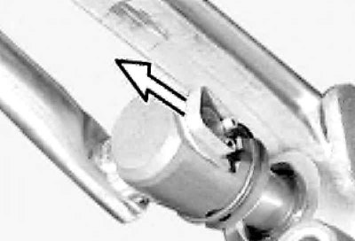
10. Insert the rubber boot with the arrow pointing forward when viewed in the direction of travel.
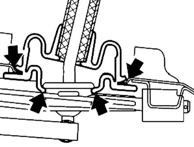
11. Push in the bearing shells by pushing against the lugs on the control arm support shaft until they lock into place.
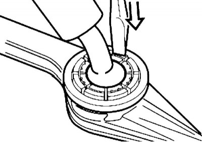
12. Lubricate the spherical part of the gear lever, insert the gear lever into the support rod and align the bearing shells: the arrows on the bearing should be directed parallel to the longitudinal axis of the car, and the protrusions holding the bearing should be perpendicular to the axis.
Replacement of a holder of a rod of a choice of transfers
1. Disconnect the cardan shaft from the manual transmission (see chapter Cardan and drive shafts, gearbox, differential and hub assemblies).
2. Remove the retaining clip.
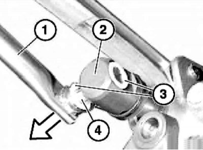
3. Take out the rod (1) gear change drive from the cage (2) selector rod and remove washers (3).
Lubricate your finger when installing (4) gear shift rods. Washer (3) should be close to the edge (2) larger plane.
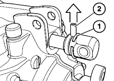
4. Hook the spring ring (1), installed in the groove and slide it back a little. Press out roll pin (2) up or down from the selector rod yoke and remove the yoke.
When installing, lubricate the spherical part of the rod and replace the snap ring (1).
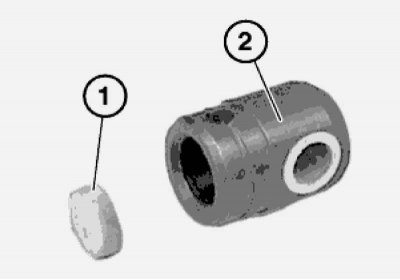
5. Check and, if necessary, replace the rubber washer (1) in the cage (2) gear selector.
6. Installation is carried out in the reverse order. Pay attention to the following points.