
Removal and installation the cylinder head
Attention:
- There should be no coolant, water or engine oil in the threaded holes of the cylinder block. Replace the cylinder head bolts.
- Do not wash off the coating from the bolts.
- Strictly observe the tightening torque and angle.
1. Remove the cylinder head cover.
2. Remove the injectors.
3. Remove the intake manifold.
4. Disconnect the negative battery cable.
5. Disconnect the exhaust turbocharger from the exhaust manifold.
6. Drain the coolant and send it for disposal.
7. Remove the EGR radiator.
8. Disconnect the coolant hoses.
9. Remove the upper chain tensioner.
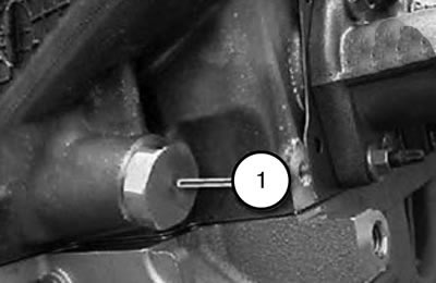
10. Unscrew the coolant drain plug on the cylinder block.
Note: The seal must be replaced during installation.
11. Turn the engine using tool 116480 in the direction of rotation until the piston of the 1st cylinder is at "TDC"
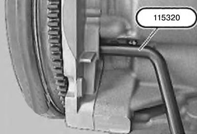
12. Fix the device 115320 on the flywheel with the piston of the 1st cylinder at the TDC end of the compression stroke.
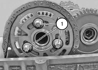
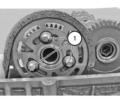
13. Loosen the bolts (1) securing the camshaft.
14. Remove the sprocket.
Attention:
- Secure the drive chain from slipping.
- Risk of damage to the oil nozzle.
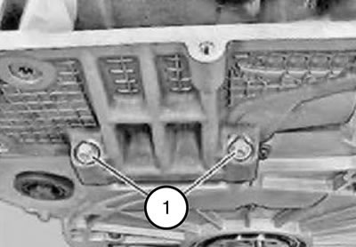
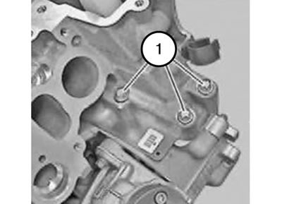
15. Unscrew the bolts (1) from the edges to the middle.
16. Remove the camshaft holder.
17. Loosen the screws (1).
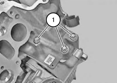
18. Remove the screws (1).
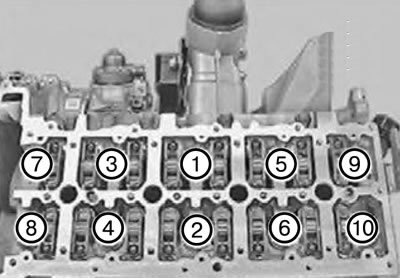
19. Loosen the cylinder head mounting bolts in sequence 10...1.
Caution: The glow plugs protrude above the cylinder head connector plane and may be damaged after removal.
Caution: Remove the cylinder head and place it down without damaging the glow plugs.
20. If necessary, remove the glow plugs using tool 116050.
Note: If no work has been performed on the cylinder block that causes a change in the piston crown protrusion, a new cylinder head gasket with the same thickness marking should be used (number of marking holes).
Note: When performing work on the crankshaft drive or pistons, it is necessary to re-determine the repair thickness of the sealing gasket.
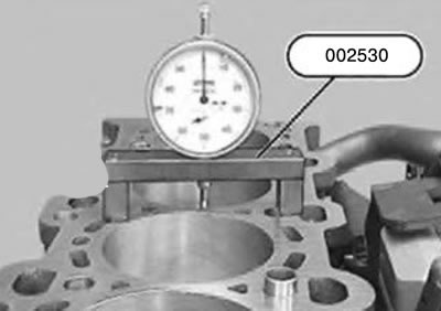
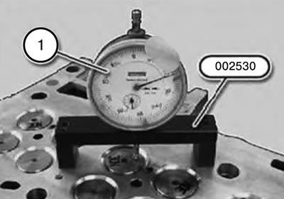
21. Measure the piston bottom protrusion relative to the cylinder block plane:
22. Install the dial indicator with measuring block, tool 002530, on the cleaned sealing surface of the cylinder head and set it to the zero mark with pre-tension.
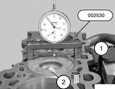
23. Clean the piston crowns at the measurement points (1 and 2).
24. Install the dial indicator on the cleaned piston at the measurement point (1) and, by turning the crankshaft, determine the highest point.
25. Measure and record the bottom protrusion at measurement points (1 and 2) for all 4 pistons.
Note: When installing, it is necessary to determine the thickness of the cylinder head gasket.
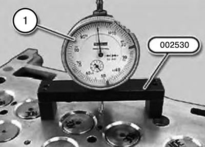
26. Install the 002530 tool with the dial indicator (1) in the required position on the cylinder head.
27. Set the dial indicator (1) to the zero mark.
28. Set the device 002530 with the dial indicator (1) to the desired position on the valve.
29. Determine the lower position of the valve.
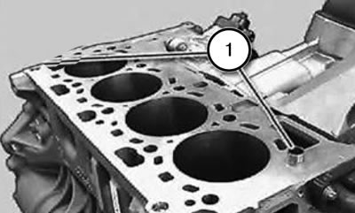
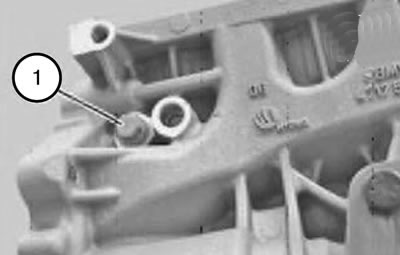
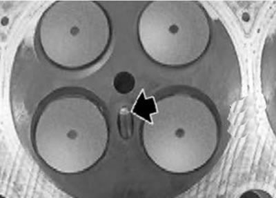
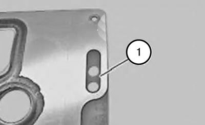
30. Check the centering bushings (1) for damage and correct installation.
31. Clean the sealing surfaces using a suitable tool.
Attention:
- There should be no coolant, water or engine oil in the threaded holes of the cylinder block. Replace the cylinder head bolts.
- Do not wash off the coating from the bolts.
- Strictly observe the tightening torque and angle.
32. Install a new cylinder head gasket of a predetermined thickness (number of marking holes).
33. Install the cylinder head and tighten with new mounting bolts in sequence 1...10.
Tightening torque: 70 Nm + 50 Nm + 120°+ 120°.
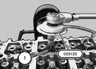
34. Tighten the cylinder head mounting bolts (1) using tool 009120.
35. Insert and tighten the bolts (1).
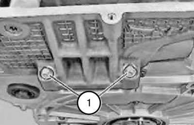
36. Insert and tighten the bolts (1).
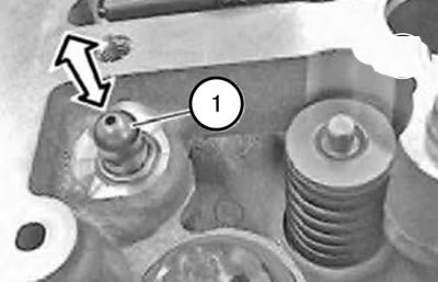
37. Pay attention to the correct position of the elements (1) HVA.
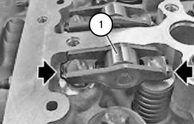
38. Pay attention to the installation position of the levers (1) of the roller pushers.
Attention:
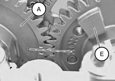
- Before installing and securing the camshaft holders to the cylinder head, the camshaft sprockets (A and E) must be installed in accordance with the markings.
- Risk of damage to engine valves.
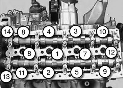
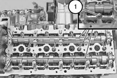
39. Install the camshaft holder on the cylinder head.
40. Tighten the bolts in sequence (1...14).
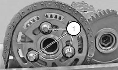
41. Install the chain sprocket with the drive chain.
42. Insert the camshaft mounting bolts (1).
43. Tighten the camshaft mounting bolts (1) to a torque of 10 Nm.
44. Loosen the camshaft mounting bolts (1) again by 90°.
45. Insert the chain tensioner (1).
46. Tighten the camshaft mounting bolts (1).
Tightening torque: 50 Nm + 120°.
47. Assemble the engine.
48. Fill the cooling system, bleed air and check for leaks.
(Information taken from this resource BMWMan)