
Table of contents: Disassembling the differential ↓ Differential assembly ↓
- Home
- BMW 3 Series
- E21
- Transmission
- Cardan and rear axle
- Disassembling the rear axle
Disassembling the rear axle (BMW 3 Series E21)
Remove the rear axle and drain the oil from the crankcase.
Remove the differential output shafts (see above).
Place alignment marks on the differential bearing caps and remove the caps. Remove the adjusting rings.
Remove the rear cover and take the differential out of the axle housing.
Apply relative position marks to the driven gear, pinion and differential case.
Remove the eight mounting bolts and remove the driven gear from the differential case.
Knock out the locking pin from the satellite axle and press out the axle.
Insert the differential output shaft and, turning it, remove the satellites from the differential box.
Remove the axle gears, support washers and adjusting washers from the differential box.
Lubricate the thrust washers and adjusting washers with hypoid gear oil.
Install the axle gear without the support and adjusting washers, the satellites into the differential box and insert the satellite shaft.
To select the adjusting washer, install the device with the indicator as shown in the photo.
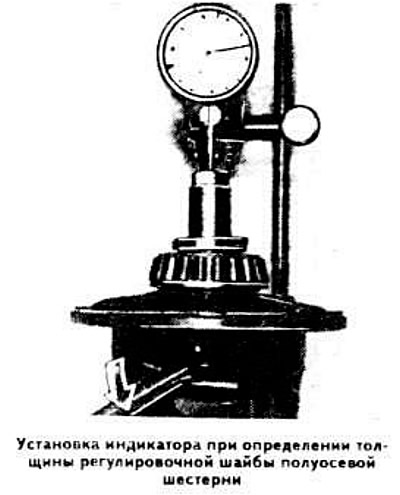
Move the axle gear sharply downwards and set the indicator arrow to zero.
Move the axle gear sharply upwards with a screwdriver and record the indicator readings. Subtract 0.05 mm from the resulting value to obtain the total thickness of the axle gear support and adjusting washers.
Repeat the above operations for the other axle gear.
Remove the satellite axle and satellites from the differential box.
Install the adjusting and support washers into the differential box, directing the latter with the convex side towards the axle gear.
Remove the indicator and, by screwing in the measuring device screw, which previously supported the indicator leg, move the axle gears apart so that the satellites can be installed in the differential box.
Insert the satellite axle and secure it with a cotter pin.
Knock the drive pinion out of the rear axle housing by hitting its end with a hammer through a lining. Press the bearings off the drive pinion.
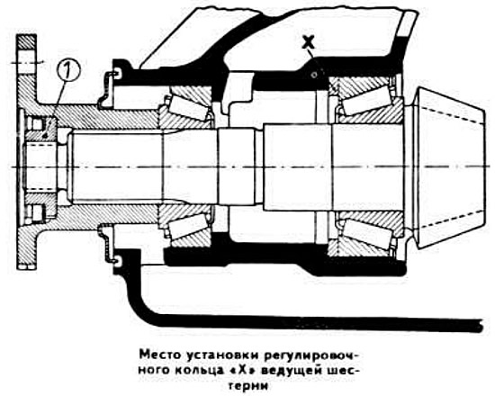
Using pullers, press out the outer bearing rings of the drive pinion from the sockets of the axle housing and remove the adjusting ring "X" from the pinion.
Remove the differential output shafts (see above).
Place alignment marks on the differential bearing caps and remove the caps. Remove the adjusting rings.
Remove the rear cover and take the differential out of the axle housing.
Disassembling the differential
Apply relative position marks to the driven gear, pinion and differential case.
Remove the eight mounting bolts and remove the driven gear from the differential case.
Knock out the locking pin from the satellite axle and press out the axle.
Insert the differential output shaft and, turning it, remove the satellites from the differential box.
Remove the axle gears, support washers and adjusting washers from the differential box.
Differential assembly
Lubricate the thrust washers and adjusting washers with hypoid gear oil.
Install the axle gear without the support and adjusting washers, the satellites into the differential box and insert the satellite shaft.
To select the adjusting washer, install the device with the indicator as shown in the photo.
Move the axle gear sharply downwards and set the indicator arrow to zero.
Move the axle gear sharply upwards with a screwdriver and record the indicator readings. Subtract 0.05 mm from the resulting value to obtain the total thickness of the axle gear support and adjusting washers.
Repeat the above operations for the other axle gear.
Remove the satellite axle and satellites from the differential box.
Install the adjusting and support washers into the differential box, directing the latter with the convex side towards the axle gear.
Remove the indicator and, by screwing in the measuring device screw, which previously supported the indicator leg, move the axle gears apart so that the satellites can be installed in the differential box.
Insert the satellite axle and secure it with a cotter pin.
Knock the drive pinion out of the rear axle housing by hitting its end with a hammer through a lining. Press the bearings off the drive pinion.
Using pullers, press out the outer bearing rings of the drive pinion from the sockets of the axle housing and remove the adjusting ring "X" from the pinion.
This article is available at russian, bulgarian, belarusian, ukrainian, serbian, croatian, romanian, polish, slovak, hungarian
Article verified: Polikarpov Saveliy
Share information:
Previous articles
БМВ E21: Cardan and rear axle
Next articles
Similar articles on other types of BMW cars:
Disassembling the rear axle BMW 5 Series E12 (1972-1981)
Rear axle propeller shaft BMW 5 Series E39 (1995-2003)
Changing the oil in the main gear (rear axle) BMW 7 Series E32 (1986-1994)
Removal and installation the rear axle gearbox BMW 7 Series E38 (1994-2001)
Checking the oil level in the rear axle gearbox and bringing it up to… BMW X3 E83 (2003-2010)
Changing the oil in the rear axle gearbox BMW X5 E53 (1999-2006)
Disassembling the rear axle BMW 5 Series E12 (1972-1981)
Rear axle propeller shaft BMW 5 Series E39 (1995-2003)
Changing the oil in the main gear (rear axle) BMW 7 Series E32 (1986-1994)
Removal and installation the rear axle gearbox BMW 7 Series E38 (1994-2001)
Checking the oil level in the rear axle gearbox and bringing it up to… BMW X3 E83 (2003-2010)
Changing the oil in the rear axle gearbox BMW X5 E53 (1999-2006)
Link in different formats to this page
Visitor comments
No comments yet
- General information
- Manual
- Maintenance
- Power unit
- Engine repair
- Cooling system
- Power system (gasoline)
- Injection system (gasoline)
- Fuel system (diesel)
- Exhaust system
- Ignition system
- Charge and launch systems
- Transmission
- Car gearbox
- Clutch and drive shafts
- Chassis
- Brake system
- Suspension front and rear
- Steering
- Body
- Body care and repair
- Exterior
- Interior
- Electrical equipment
- Troubleshooting
- Lighting and signaling
- Equipment and devices
- Heater and air conditioner
- Electrical circuits
- General information
- Manual
- Repair on the road
- Weekly checks
- Maintenance
- Troubleshooting
- Power unit
- 4 cylinder engines
- 6 cylinder engines
- Engine overhaul
- Cooling and heating
- Fuel and exhaust system
- Starting and charging system
- Ignition system
- Transmission
- Clutch
- Mechanical gearbox
- Automatic gearbox
- Cardan and drive shafts
- Chassis
- Brake system
- Wheel suspension
- Steering
- Body
- Exterior
- Interior
- Electrical equipment
- Equipment and devices
- Electrical circuits
- General information
- Maintenance
- Power unit
- Engine repair
- Cooling system
- Ignition system
- Supply system
- Fuel injection system
- Exhaust system
- Transmission
- Clutch
- Car gearbox
- Front and rear axle
- Chassis
- Steering
- Brake system
- Body
- Exterior
- Interior
- Electrical equipment
- Heating system
- Equipment and devices
- Power devices
- Electrical circuits
- Power unit
- M10/M20 engine
- M40 engine
- Ignition system
- Lubrication system
- Cooling system
- Supply system
- Fuel injection
- Exhaust system
- Transmission
- Clutch
- Manual gearbox
- Front axle
- Rear axle
- Chassis
- Steering
- Brake system
- Body
- Exterior
- Interior
- Electrical equipment
- Heating system
- Equipment and devices
- Electrical circuits
- General information
- Specifications
- Operation and maintenance
- 4-cylinder engine
- Engine repair
- Cooling and lubrication system
- Supply system
- Ignition system
- 6-cylinder engine
- Engine repair
- Cooling and lubrication system
- Supply system
- Fuel injection system
- Ignition system
- Transmission
- Clutch
- 4-speed manual gearbox
- 5-speed manual gearbox
- Automatic gearbox
- Cardan and rear axle
- Chassis
- Steering
- Front suspension
- Rear suspension
- Brake system
- Electrical equipment
- Equipment and devices
- Electrical circuits