
Table of contents: Removal ↓ Installation ↓
- Home
- BMW 3 Series
- E36
- Power unit
- Supply system
- Removal and installation injectors
Removal and installation injectors (BMW 3 Series E36)
The injectors provide conical fuel injection and after injection are hermetically sealed. If the injectors are not hermetically sealed, starting a hot engine is difficult. If the injectors are defective, the engine becomes diesel and its operation is uneven.
Remove the outside air supply duct to the heater from the bulkhead.
Use a narrow screwdriver to pull out the "arrow" plugs and unscrew the bolts located underneath them.
Unscrew the oil filler cap and remove the 2 upper plastic covers from the engine.
Loosen the hose clamp "4" and disconnect the fuel supply hose from the distribution pipe.
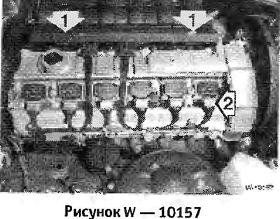
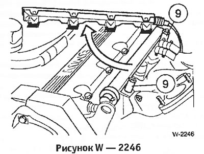
Unscrew bolts "1" and disconnect the connector block from the injectors.

Loosen the bolts securing the "arrow" of the fuel distribution pipe. (Unlike the image in the picture, the engine cover has been removed).
Remove the air hose from the throttle valve fitting.
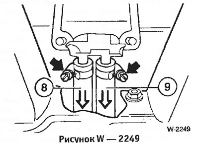
Unscrew bolts "7" and nuts "8".
Loosen bolts 5 and 6. Press the intake air heater down. The heater is included in the engine cooling circuit. Leave the hoses connected. Pay attention to the position of the sealing ring for subsequent installation.
Pull out and fold back the upper part of the intake manifold.
Remove the connector block from the injectors.
Remove bolts "9" from the fuel distribution pipe.
Disconnect the air hose from the throttle valve fitting.
Disconnect the throttle cable.
Disconnect the vacuum hose from the brake booster.
Disconnect the 2 water hoses from the throttle body heater and plug the hoses with plugs such as clean screws.
Disconnect the throttle switch connector "1" by pressing the wire retainer.
Disconnect vacuum hoses "2".
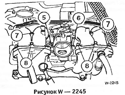
Unscrew 4 bolts "3" (only 2 of them are visible in the picture) and carefully remove the throttle valve fitting.
Unscrew the front and rear supports of the manifold "4".
Unscrew the idle speed control valve "5".
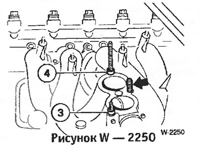
Unscrew 3 bolts and remove the upper part of the manifold. Pay attention to the location of the centering bushings "3" and "4" for subsequent installation.
Disconnect the connector block from the injectors and unscrew the bolts from the fuel distribution pipe (Figure W 2246).
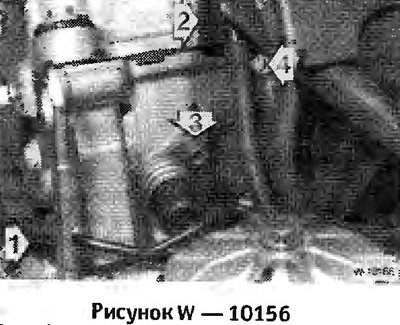
Six-cylinder engine: Disconnect vacuum hose "1" from the fuel pressure regulator.
Disconnect fuel hose "2" from the fuel distribution pipe, having first released the clamp; collect the leaking fuel with a rag.
Pull the fuel distribution pipe together with the injectors out of the cylinder head. The injectors are simply inserted and can be easily removed.
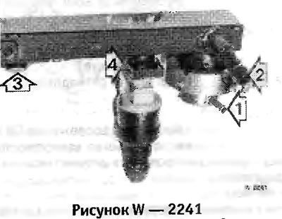
Pull the clamps "4" to the side and remove the injectors.
Insert the injectors into the fuel distribution pipe and secure with clamps.
Insert the injectors together with the fuel distribution pipe into the cylinder head. Before installation, lubricate the sealing rings with Vaseline and SAE 90 gearbox lubricant.
Secure the fuel rail to the cylinder head with two bolts.
Connect the fuel hoses.
Place the connector block on the injectors.
Secure the connector block with 2 bolts.
Install the engine cover.
Screw on the upper part of the intake manifold with new gaskets, while not forgetting to install the centering bushings. Tighten the bolts evenly with a torque of 20 Nm.
Screw on the manifold supports and the idle speed control valve, see the figure in the "Removal" subsection.
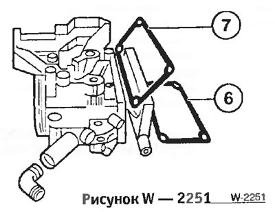
Screw on the throttle valve fitting with new gaskets "6" and "7".
Connect 2 water hoses and secure the hoses with clamps. If coolant leaked during removal, top up to the normal level.
Connect 2 vacuum hoses to the throttle valve fitting and a vacuum hose to the brake booster.
Connect the throttle potentiometer connector, it should snap into place.
Connect the throttle cable.
Install the air hose.
Start the engine and check the intake tract for leaks, see the section "Checking the idle speed/CO content".
Install an outside air supply duct on the bulkhead.
Remove the injectors. The injectors and fuel hoses remain on the fuel rail.
Place the connector block on the injector.
Place the nozzles in a suitable measuring vessel.
The assistant should turn on the starter for a few seconds and compare the injection streams of the individual injectors. The injection stream should be conical and of the same type on all injectors
Turn off the ignition.
Remove the connector block from the injectors.
Turn on the ignition for about 5 seconds without turning on the starter. After that, check the density: no more than one drop of fuel should come out of the injector within 1 minute.
Install the injectors.
Check the power supply. To do this, remove the connector from the injector and connect a diode tester to the contacts of a suitable cable. Turn on the starter (assistant). The LED should light up.
If the LED does not light, the cause of the defect may be a broken wire or a failure of the control unit.
Turn off the ignition.
Connect an ohmmeter to the contacts on the connector of each injector and measure the resistance. See the specified value below.
Replace defective injectors.
You can read the original on the website: BMWMAN
Removal
Remove the outside air supply duct to the heater from the bulkhead.
Models 320i, 325i, 328i (Six-cylinder engine)
Use a narrow screwdriver to pull out the "arrow" plugs and unscrew the bolts located underneath them.
Unscrew the oil filler cap and remove the 2 upper plastic covers from the engine.
Loosen the hose clamp "4" and disconnect the fuel supply hose from the distribution pipe.
Warning: The fuel system is under pressure. When disconnecting the hose, use a rag to wipe off any leaking fuel. Fire hazard!
Unscrew bolts "1" and disconnect the connector block from the injectors.
Loosen the bolts securing the "arrow" of the fuel distribution pipe. (Unlike the image in the picture, the engine cover has been removed).
Models 316i, 318i produced before August 1993.
Remove the air hose from the throttle valve fitting.
Unscrew bolts "7" and nuts "8".
Loosen bolts 5 and 6. Press the intake air heater down. The heater is included in the engine cooling circuit. Leave the hoses connected. Pay attention to the position of the sealing ring for subsequent installation.
Pull out and fold back the upper part of the intake manifold.
Remove the connector block from the injectors.
Remove bolts "9" from the fuel distribution pipe.
Models 316i, 318i produced since September 1993, 318is/ti
Disconnect the air hose from the throttle valve fitting.
Disconnect the throttle cable.
Disconnect the vacuum hose from the brake booster.
Disconnect the 2 water hoses from the throttle body heater and plug the hoses with plugs such as clean screws.
Disconnect the throttle switch connector "1" by pressing the wire retainer.
Disconnect vacuum hoses "2".
Unscrew 4 bolts "3" (only 2 of them are visible in the picture) and carefully remove the throttle valve fitting.
Note: Adjustment of the throttle valve is not possible. If damaged, for example by impacts, the throttle valve nipple must be replaced.
Unscrew the front and rear supports of the manifold "4".
Unscrew the idle speed control valve "5".
Unscrew 3 bolts and remove the upper part of the manifold. Pay attention to the location of the centering bushings "3" and "4" for subsequent installation.
Disconnect the connector block from the injectors and unscrew the bolts from the fuel distribution pipe (Figure W 2246).
Six-cylinder engine: Disconnect vacuum hose "1" from the fuel pressure regulator.
Disconnect fuel hose "2" from the fuel distribution pipe, having first released the clamp; collect the leaking fuel with a rag.
Pull the fuel distribution pipe together with the injectors out of the cylinder head. The injectors are simply inserted and can be easily removed.
Pull the clamps "4" to the side and remove the injectors.
Installation
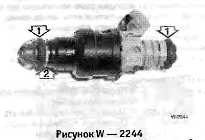
Caution: When installing the injectors, do not damage the O-rings "1". Replace defective rings, taking into account the installation position of the sealing ring "2". Before installation, lubricate the sealing rings with Vaseline or SAE90 gearbox grease.
Insert the injectors into the fuel distribution pipe and secure with clamps.
Insert the injectors together with the fuel distribution pipe into the cylinder head. Before installation, lubricate the sealing rings with Vaseline and SAE 90 gearbox lubricant.
Secure the fuel rail to the cylinder head with two bolts.
Connect the fuel hoses.
Place the connector block on the injectors.
Models 320i, 325i, 328i
Secure the connector block with 2 bolts.
Install the engine cover.
Models 316i, 318i produced before August 1993, 318is/ti
Screw on the upper part of the intake manifold with new gaskets, while not forgetting to install the centering bushings. Tighten the bolts evenly with a torque of 20 Nm.
Screw on the manifold supports and the idle speed control valve, see the figure in the "Removal" subsection.
Screw on the throttle valve fitting with new gaskets "6" and "7".
Connect 2 water hoses and secure the hoses with clamps. If coolant leaked during removal, top up to the normal level.
Connect 2 vacuum hoses to the throttle valve fitting and a vacuum hose to the brake booster.
Connect the throttle potentiometer connector, it should snap into place.
Connect the throttle cable.
Install the air hose.
Start the engine and check the intake tract for leaks, see the section "Checking the idle speed/CO content".
Install an outside air supply duct on the bulkhead.
Checking the injectors
Remove the injectors. The injectors and fuel hoses remain on the fuel rail.
Place the connector block on the injector.
Place the nozzles in a suitable measuring vessel.
The assistant should turn on the starter for a few seconds and compare the injection streams of the individual injectors. The injection stream should be conical and of the same type on all injectors
Turn off the ignition.
Remove the connector block from the injectors.
Turn on the ignition for about 5 seconds without turning on the starter. After that, check the density: no more than one drop of fuel should come out of the injector within 1 minute.
Install the injectors.
Checking power supply and resistance
Check the power supply. To do this, remove the connector from the injector and connect a diode tester to the contacts of a suitable cable. Turn on the starter (assistant). The LED should light up.
If the LED does not light, the cause of the defect may be a broken wire or a failure of the control unit.
Turn off the ignition.
Connect an ohmmeter to the contacts on the connector of each injector and measure the resistance. See the specified value below.
Replace defective injectors.
You can read the original on the website: BMWMAN
This article is available at russian, bulgarian, belarusian, ukrainian, serbian, croatian, romanian, polish, slovak, hungarian
Article verified: Chebotarev Vladislav
Share information:
Previous articles
БМВ E36: Supply system
Next articles
Similar articles on other types of BMW cars:
Removal and installation valve injectors BMW 5 Series E39 (1995-2003)
Removal and installation the oil pan BMW 5 Series E12 (1972-1981)
Injectors — removal and installation BMW 7 Series E32 (1986-1994)
Removal and installation of fuel distribution line and injectors BMW 7 Series E38 (1994-2001)
Pistons — removal and installation BMW X3 E83 (2003-2010)
Removal and installation of injectors BMW X5 E53 (1999-2006)
Link in different formats to this page
Visitor comments
No comments yet
- General information
- Manual
- Maintenance
- Power unit
- Engine repair
- Cooling system
- Power system (gasoline)
- Injection system (gasoline)
- Fuel system (diesel)
- Exhaust system
- Ignition system
- Charge and launch systems
- Transmission
- Car gearbox
- Clutch and drive shafts
- Chassis
- Brake system
- Suspension front and rear
- Steering
- Body
- Body care and repair
- Exterior
- Interior
- Electrical equipment
- Troubleshooting
- Lighting and signaling
- Equipment and devices
- Heater and air conditioner
- Electrical circuits
- General information
- Manual
- Repair on the road
- Weekly checks
- Maintenance
- Troubleshooting
- Power unit
- 4 cylinder engines
- 6 cylinder engines
- Engine overhaul
- Cooling and heating
- Fuel and exhaust system
- Starting and charging system
- Ignition system
- Transmission
- Clutch
- Mechanical gearbox
- Automatic gearbox
- Cardan and drive shafts
- Chassis
- Brake system
- Wheel suspension
- Steering
- Body
- Exterior
- Interior
- Electrical equipment
- Equipment and devices
- Electrical circuits
- General information
- Maintenance
- Power unit
- Engine repair
- Cooling system
- Ignition system
- Supply system
- Fuel injection system
- Exhaust system
- Transmission
- Clutch
- Car gearbox
- Front and rear axle
- Chassis
- Steering
- Brake system
- Body
- Exterior
- Interior
- Electrical equipment
- Heating system
- Equipment and devices
- Power devices
- Electrical circuits
- Power unit
- M10/M20 engine
- M40 engine
- Ignition system
- Lubrication system
- Cooling system
- Supply system
- Fuel injection
- Exhaust system
- Transmission
- Clutch
- Manual gearbox
- Front axle
- Rear axle
- Chassis
- Steering
- Brake system
- Body
- Exterior
- Interior
- Electrical equipment
- Heating system
- Equipment and devices
- Electrical circuits
- General information
- Specifications
- Operation and maintenance
- 4-cylinder engine
- Engine repair
- Cooling and lubrication system
- Supply system
- Ignition system
- 6-cylinder engine
- Engine repair
- Cooling and lubrication system
- Supply system
- Fuel injection system
- Ignition system
- Transmission
- Clutch
- 4-speed manual gearbox
- 5-speed manual gearbox
- Automatic gearbox
- Cardan and rear axle
- Chassis
- Steering
- Front suspension
- Rear suspension
- Brake system
- Electrical equipment
- Equipment and devices
- Electrical circuits