
Information about diagnostic tools
Checking the correct functioning of the components of the injection systems and reducing the toxicity of exhaust gases is carried out using a universal digital meter (multimeter) (see illustration below). The use of a digital meter is preferred for several reasons. Firstly, it is quite difficult for analog devices to (sometimes impossible), to determine the result of the indication with an accuracy of hundredths and thousandths, while when examining circuits that include electronic components, such accuracy is of particular importance. The second, no less important, reason is the fact that the internal circuit of a digital multimeter has a fairly high impedance (the internal resistance of the device is 10 mΩ). Since the voltmeter is connected in parallel to the circuit under test, the measurement accuracy is higher, the smaller the current will pass through the device itself. This factor is not significant when measuring relatively high voltage values (9÷12 V), however, it becomes decisive in the diagnosis of elements that produce low-voltage signals, such as, for example, a lambda probe, where we are talking about measuring fractions of a volt.
Parallel monitoring of signal parameters, resistances and voltages in all control circuits is possible using splitter, connected in series to the connector of the engine control unit. At the same time, with the engine turned off, running or while the car is moving, the parameters of the signals at the splitter terminals are measured, from which a conclusion is made about possible defects.
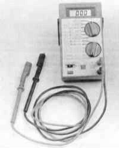
The use of a high-impedance digital multimeter in the diagnostics of the systems under consideration significantly increases the accuracy of measurements
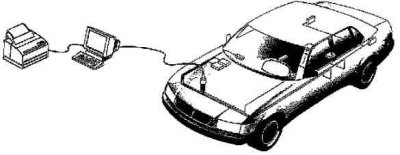
To diagnose electronic systems of the engine, automatic transmission, ABS, SRS, special diagnostic scanners or BMW testers can be used DIS, MoDIC (PC-programmable). In addition, scanners and specialized diagnostic analyzers can be used for this purpose, for example CS 1000, Bosch FSA 560, KTS 300 (HAMMER), Sun 2013, or a regular personal computer with a special adapter, cable and OBD browser installed (for example, the Bosch ESI [tronic] program in Russian, the Car Scanner program.
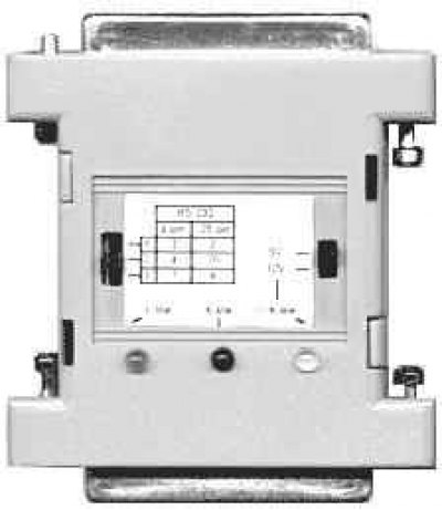
Universal adapter KL-line, used to match the signals of the RS-232 port and ISO-9141 interfaces (K-line) and ALDL. Various cables can be connected to the adapter connectors, which are necessary for diagnosing a particular brand of car. The switches and display elements installed in the adapter allow you to select the required operating modes and roughly evaluate the operation of the output lines. So, the glow of the green LED with the L-line marking indicates the connection of the L line with the car body. The glow of the red LED with the K-line marking indicates a high potential that is present at that moment on the K line. When the connection with the car is established, the blinking of the indicators may not be noticeable to the eye due to the high exchange rate. Connection to a computer is made directly to the 25-pin COM port or using "RS-232 cable 25 pins - 9 cont." to the 9-pin COM port.
Some scanners, in addition to the usual diagnostic operations, allow, when connected to a personal computer, to print circuit diagrams of electrical equipment stored in the memory of the control unit (if laid down), program the anti-theft system, observe the signals in the car circuits in real time.
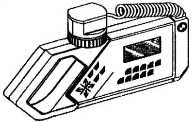
Hand-held scanners MoDIC, KTS 300 can be used to diagnose the electronic control of vehicle systems (Bosch) or a personal computer.
Adapter for matching lines K and L diagnostics with PC COM port
Reading of the codes of malfunctions written down in memory of system of self-diagnostics on some models can be made also on the indicator "check engine" on the dashboard.
PC connection for vehicle diagnostics
For diagnostics, for example, devices from ToolRama, Inc. can also be used. (3500 NW Boca Raton Blvd., Boca Raton, Florida, 33431, USA 1 877 866 5726 - 561 750 4511 - 561 338 8447 FAX) with cartridges for a specific car model.
All tester cartridges can also be used in the scanner. In this case, the functions will be limited to only reading and clearing memory.
- tester R000 with cartridge T051A (B or C) or P000 scanner with T041 cartridge,
- universal cable N000,
- connector N001.
The scanner only reads the entered fault memory and clears the fault memory. The tester can additionally activate and display the current data.
The OBD II cartridge performs the following functions:
- Reading and clearing OBD II trouble codes. Displays oxygen sensor test results.
- Continuous monitoring of ignition, injection and component systems.
- Displaying a list of current data and fixed transient failures:
- Absolute pressure in the inlet pipeline;
- Oxygen sensor voltage;
- Engine coolant temperature;
- Estimated engine load;
- vehicle speed;
- fuel quality;
- Air flow (by weight);
- Ignition advance;
- Throttle position;
- Intake air temperature.
You can get acquainted with details about devices on the sites programatools.com, bosch.de.
General description of the OBD self-diagnosis system
The OBD system includes several diagnostic devices that monitor individual parameters of the toxicity reduction systems and fix the detected failures in the on-board processor memory in the form of individual fault codes. The system also checks sensors and actuators, controls vehicle maintenance cycles, provides the ability to store even short-term failures during operation and clear the memory block.
Some of the models described in this manual are equipped with an on-board diagnostic system. The main element of the system is the onboard processor, often called the electronic control module (ECM), or a power unit operation control module (RSM). The PCM is the brain of the engine management system. The initial data is fed to the module from various information sensors and other electronic components (switches, relays, etc.).
Based on the analysis of the data coming from the information sensors, and in accordance with the basic parameters stored in the processor memory, the PCM generates commands for the operation of various control relays and actuators, thereby adjusting the operating parameters of the engine and ensuring maximum efficiency of its output with minimal fuel consumption.
The OBD processor memory data is read using a special scanner connected to the 20-pin diagnostic connector located on the left in the engine compartment.
The black, 20-pin diagnostic connector X 1532 is located in the left rear of the engine compartment, to the right of the shock strut dome (arrow). M30 engine shown
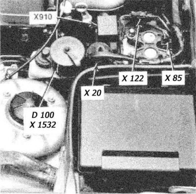
D100 - Diagnostic connector
X20 - 20-pin SW connector
X85 - 3-pin SW connector
X122- 2-pin connector SW
X1532 - 20-pin SW connector
X910 - Connector
In principle, the fault codes stored in the memory of the self-diagnosis system can be read using a lamp "Check engine" (refer to Section Reading fault codes).
Pin assignment of the 20-pin diagnostic connector
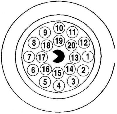
1 - Engine speed signal
4 - Temperature sensor voltage
7 - Reset Service Interval Indicator - Dashboard
11 - Starter - ignition switch (12V at startup)
12 - Generator charging indicator (cont. 61D)
14 - Ignition switch (cont. thirty). Always energized
15 - Line L start diagnostics (RxD receive data)
16 - Ignition lock (cont. 15). Energized in the Run and Start positions
17 - Line K diagnostic data (TxD II - data transmission)
18 - DME program selection voltage
19 - Housing (cont. 31)
20 - Line K diagnostic data (TxD - data transfer)
Information sensors
oxygen sensors (lambda probes) - The sensor generates a signal whose amplitude depends on the difference in oxygen content (O2) in engine exhaust gases and outside air before and after the catalytic converter.
crankshaft position sensor (TFR) - The sensor informs the PCM about the position of the crankshaft and the engine speed. This information is used by the processor when determining fuel injection timing and setting the ignition timing.
Piston position sensor (CYP) - Based on the analysis of the signals coming from the sensor, the PCM calculates the position of the piston of the first cylinder and uses this information to determine the moments and sequence of fuel injection into the engine's combustion chambers.
TDC sensor (TDC) - The signals generated by the sensor are used by the PCM in determining the ignition timing settings at the time of engine start.
Engine coolant temperature sensor (EATING) - Based on the information coming from the sensor, the ECM / PCM makes the necessary adjustments to the composition of the air-fuel mixture and the ignition timing, and also monitors the operation of the EGR system.
intake air temperature sensor (IAT) - The PCM uses information from the IAT sensor to make adjustments to fuel flow, ignition timing settings, and to control the operation of the EGR system.
Throttle position sensor (TPS) - The sensor is located on the throttle body and connected to the throttle shaft. Based on the amplitude of the TPS signal output, the PCM determines the throttle opening angle (controlled by the driver from the gas pedal) and adjusts the fuel supply to the inlet ports of the combustion chambers accordingly. The failure of the sensor, or the weakening of its fastening, leads to interruptions in injection and violations of the stability of the idle speed.
Absolute pressure sensor in the pipeline (IDA) - The sensor monitors variations in the depth of vacuum in the intake manifold associated with changes in crankshaft speed and engine load and converts the information received into an amplitude signal. The PCM uses the information provided by the MAP and IAT sensors to make subtle fuel adjustments.
Atmospheric pressure sensor - The sensor generates an amplitude signal proportional to changes in atmospheric pressure, which is used by the PCM to determine the duration of the fuel injection moments. The sensor is built into the PCM and cannot be serviced individually.
Knock sensor - The sensor reacts to changes in the level of vibrations associated with detonations in the engine. Based on the information coming from the sensor, the PCM performs an appropriate adjustment of the ignition timing.
Vehicle speed sensor (VSS) - As its name implies, the sensor informs the processor about the current vehicle speed.
EGR valve opening sensor - The sensor notifies the PCM of the amount of displacement of the EGR valve plunger. The information received is then used by the processor when controlling the operation of the exhaust gas recirculation system.
Fuel tank pressure sensor - The sensor is an integral element of the fuel vapor recovery system (EVAP) and serves to monitor the vapor pressure of gasoline in the tank. Based on the information coming from the sensor, the PCM issues commands to operate the system purge solenoid valves.
Power steering pressure switch (PSP) - Based on the information coming from the PSP sensor-switch, the PCM provides an increase in idle speed due to the operation of the IAC sensor in order to compensate for the increased engine loads associated with the operation of the power steering during maneuvers.
Transmission sensors - In addition to the data from the VSS, the PCM also receives information from sensors placed inside the transmission or connected to it. These sensors include: (A) secondary speed sensor (indigenous) shaft and (b) intermediate shaft speed sensor.
Sensor-switch for controlling the inclusion of the clutch clutch of the air conditioner - When battery power is applied to the K / V compressor solenoid valve, the corresponding information signal is sent to the PCM, which regards it as evidence of an increase in the load on the engine and adjusts its idling speed accordingly.
Executive devices
Main relay PGM-FI (fuel pump relay) - The PCM activates the fuel pump relay when the ignition key is turned to the START or RUN position. When the ignition is turned on, the activation of the relay provides a pressure rise in the power system. For more information on the main relay, see Chapter Supply system.
fuel injectors - PCM ensures that each of the injectors is switched on individually in accordance with the established firing order. In addition, the module controls the duration of the opening of the injectors, determined by the width of the control pulse, measured in milliseconds, which determines the amount of fuel injected into the cylinder. More detailed information on the principle of operation of the injection system, replacement and maintenance of injectors is given in Chapter Supply system.
Ignition control module (ICM) - The module controls the functioning of the ignition coil, determining the required basic advance based on the commands generated by the PCM. On all models of cars considered in this Manual, the ICM built into the ignition distributor is used, for more details see Chapter Ignition system.
Idle speed control valve (IAC) - The IAC valve controls the amount of air bypassing the throttle when the throttle is closed or in the idle position. The opening of the valve and the formation of the resulting air flow is controlled by the PCM.
Carbon canister purge solenoid valve - The valve is an integral part of the fuel vapor recovery system (EVAP) and, triggered by the command of the PCM, releases the fuel vapors accumulated in the adsorber into the intake pipeline in order to burn them during the normal operation of the engine.
Carbon canister purge control solenoid - The solenoid is used by the PCM when the OBD-II system checks that the EVAP system is functioning properly.
Reading fault codes
If a malfunction is detected that repeats in a row in two trips, the PCM issues a command to turn on the indicator lamp mounted in the instrument panel "Check engine", also called the failure indicator. The lamp will continue to burn until the memory of the self-diagnosis system is cleared of the fault codes entered in it. Reading fault codes in the OBD system can be done in various ways. The main way is to read using the devices described above connected to the DLC connector of the OBD system. Other methods are not available on all models. Flashing code can be read by lamp "Check engine".
Without starting the engine, turn on the ignition - control lamp "Check engine" should light up, otherwise it should be replaced.
On early models, if there is a problem, the warning lamp will flash several times for 1 second and then go out before turning on permanently. Number of lamp flashes (1 to 4) corresponds to the fault code (the list below).
Method for reading flashing codes by lamp "Check engine" (available on some models)
Diagram of issuing a flashing code by a control lamp
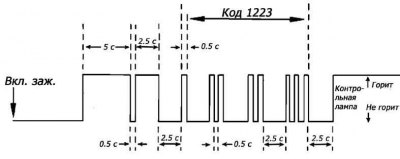
Turn on the ignition. Fully depress and release the accelerator pedal five times within five seconds. If the codes of the faults that have occurred are entered in the processor memory, they will start to be sequentially displayed by the control lamp "Check engine" on the dashboard of a car. Read the flashing code.
The lamp lights up for 5 seconds, after 0.5 seconds it lights up again for 2.5 seconds, and after an interval of 2.5 seconds a code is issued. The value of each digit of the code corresponds to the number of flashes with an interval of 0.5 seconds. First, the most significant digits of the code are issued, the last ones are units. Intervals between code bits - 2.5 sec. After the code is issued, the lamp remains on. Repeat the procedure to read subsequent codes. If the first issued code is 1444, 2444 or 4444, no malfunctions are recorded.
Codes 1000 or 2000, issued by one or two flashes and a long pause, and then a constant burning of the lamp, indicate the end of the issuance of the code.
Starting the engine automatically terminates access to the diagnostic system.
Clearing the OBD memory
When a fault code is entered into the PCM memory, a control lamp lights up on the dashboard of the car "Check engine". The code remains stored in the module's memory.
To clear the ECM memory, connect a scanner to the system and select the CLEARING COEDS function from its menu (Deleting codes). Then follow the instructions displayed on the device, or immediately remove the EFI fuse from its socket in the mounting block for 30 seconds.
Alternatively, system memory can be cleared by removing the fuse link (the main fuse of the onboard power supply system), installed near the positive battery terminal (you can also just disconnect the positive wire from the battery).
Please note that clearing the OBD memory by disconnecting the negative cable from the battery will erase the engine settings and cause engine rpm to become unstable for a short time after the initial start.
If your vehicle's stereo system is equipped with a security code, before disconnecting the battery, make sure you have the correct combination to activate the audio system!
Disconnecting the battery also deletes the receiver's favorite radio stations.
To avoid damage to the ECM, disconnect and connect it only with the ignition off!
Make sure that the system memory is cleared before installing new emission control system components on the engine. If the fault memory is not cleared before starting the system after replacing a failed information sensor, the PCM will enter a new fault code into it. Clearing memory allows the processor to reconfigure to new parameters. In this case, in the first 50 ÷ 20 minutes after the initial start of the engine, some violation of the stability of its revolutions may occur.
Fault codes
Motronic 1.1, 1.2, 1.3 - failure lamp flashes
| 1 | Air flow sensor |
| 2 | Lambda probe |
| 3 | coolant temperature sensor |
| 4 | Throttle closed position switch |
Motronic 1.1, 1.2, 1.3
| 1 | Electronic control unit |
| 3 | Fuel Pump Relay Circuit |
| 5 | Idle speed control valve circuit |
| 7 | Air flow meter |
| 10 | Mixture quality control, lambda sensor |
| 15 | Failure warning lamp |
| 16 | Injectors for cylinders 1, 3, 5 |
| 17 | Injectors for cylinders 2, 4, 6 |
| 23 | Heated lambda probe or its relay |
| 28 | lambda probe circuit |
| 29 | Engine speed sensor |
| 33 | Kick-down valve |
| 37 | Power supply of the electronic control unit above 16V |
| 43 | CO adjustment potentiometer |
| 44 | Air temperature sensor |
| 45 | coolant temperature sensor |
| 51 | Ignition advance offset |
| 52 | Throttle position switch |
| 53 | Throttle position switch |
| 54 | AT rotation converter blocking |
| 100 | Ignition booster |
| 101 | Engine failure |
Diagnostic codes for DME 1.7 systems (518i), read with a tester
| 1 | Fuel pump relay or its circuit to the control unit (output 1) |
| 3 | Break, short circuit of a chain of injectors 1 and 3 |
| 8 | Short circuit of a chain of a control lamp "Check engine" |
| 12 | Open, short circuit of the throttle potentiometer circuit |
| 16 | Camshaft position sensor. Disappearance of signal at 2500 rpm. |
| 29 | Short circuit in the control circuit x.x., (conclusion 29) |
| 32 | Break, short circuit of a chain of injectors 2 and 4 |
| 36 | Open, short circuit in the fuel tank ventilation valve circuit |
| 37 | Break, short circuit of the lambda probe heating circuit, (conclusion 37) |
| 41 | Open, short circuit of the airflow meter circuit |
| 54 | The supply voltage of the control unit is below 9V or above 16V |
| 70 | Open, short circuit lambda probe circuit |
| 73 | Incorrect vehicle speed sensor signal |
| 77 | Open, short circuit in intake air temperature sensor circuit |
| 78 | Open, short circuit in coolant temperature sensor circuit |
| 85 | Air conditioning compressor. Open circuit at pin 86 and short circuit at pin 85 |
| 100 | Ignition Final Stage Output Communication Lost |
| 200 | Internal memory defect of the control unit |
| 201 | Too rich or too lean mixture in the last 8 seconds |
DME 3.1 System Diagnostic Codes (520i, 525), read with a tester
| 0 | Undefined fault in block memory |
| 1 | Fuel pump relay or its circuit to the control unit (output 1) |
| 2 | Break, short circuit of the activator x.x. (closed) or its circuit to the control unit (output 2) |
| 3 | Break, short circuit of the injector 1 circuit to the control unit (conclusion 3) |
| 4 | Break, short circuit of the injector 3 circuit to the control unit (output 4) |
| 5 | Break, short circuit of the injector 2 circuit to the control unit (conclusion 5) |
| 6 | Breakage or short circuit of chains of injectors |
| 8 | Breakage or short circuit of a chain of a control lamp "Check engine" |
| 12 | Open or short in throttle potentiometer circuit |
| 16 | Camshaft position sensor signal |
| 18 | Short circuit to the case or positive output 18 of the control unit |
| 19 | Short circuit to the case or positive output 19 of the control unit |
| 23 | Cylinder 2 ignition coil output open (conclusion 23) |
| 24 | Cylinder 3 ignition coil output open (conclusion 24) |
| 25 | Cylinder 1 ignition coil output open (conclusion 25) |
| 26 | The control unit supply voltage is lower than the battery voltage (with engine off) |
| 29 | Short circuit in the activator circuit x.x. (open), (conclusion 29) |
| 31 | Break, short circuit of the injector 5 circuit to the control unit (conclusion 31) |
| 32 | Break, short circuit of the injector 6 circuit to the control unit (conclusion 32) |
| 33 | Break, short circuit of the injector 4 circuit to the control unit (conclusion 33) |
| 34 | Break, short circuit of chains of components to the control unit |
| 36 | Open, short circuit in the fuel tank ventilation valve circuit |
| 37 | Open, short circuit of the lambda probe heating circuit |
| 41 | Open, short circuit of the air mass meter circuit |
| 46 | Short circuit to the case or positive output 46 of the control unit |
| 48 | The air conditioning compressor does not turn off at speeds below 8 km/h |
| 50 | Cylinder 4 ignition coil output open (conclusion 50) |
| 51 | Cylinder 6 ignition coil output open (conclusion 51) |
| 52 | Cylinder 5 ignition coil output open (conclusion 52) |
| 54 | Control unit supply voltage below 10V or above 14V |
| 55 | Break in the ignition circuits |
| 64 | Ignition advance circuit - short circuit to the terminal housing 64 of the control unit |
| 67 | No RPM/Crankshaft Position Sensor Signal, Ignition and Injection Off |
| 70 | Open, short circuit lambda probe circuit |
| 73 | Vehicle speed sensor |
| 77 | Open, short circuit in intake air temperature sensor circuit |
| 78 | Open, short circuit in coolant temperature sensor circuit |
| 81 | Operation of the anti-theft alarm after starting the engine |
| 85 | Air conditioning compressor operation after engine start, while the switch signal was not received |
| 100 | Short circuit to the case or positive output 100 of the control unit |
| 200 | Internal defect of the RAM or ROM / PROM of the control unit |
| 201 | Internal defect in fault memory |
| 202 | Exhaust toxicity management out of control |
Diagnostic codes for Motronic M3.3 systems (540i)
| 1211 | The engine control unit |
| 1212 | Lambda probe 2 |
| 1213 | Lambda probe 2 signal out of control |
| 1215 | Air mass/air flow meter |
| 1216 | Throttle Potentiometer |
| 1221 | Lambda probe 1 |
| 1222 | Lambda probe 1 signal out of control |
| 1223 | coolant temperature sensor |
| 1224 | intake air temperature sensor |
| 1225 | Knock sensor 1 |
| 1226 | knock sensor 2 |
| 1227 | knock sensor 3 |
| 1228 | Knock sensor 4 |
| 1231 | Supply voltage |
| 1232 | Throttle closed position switch |
| 1233 | Throttle position sensor-switch |
| 1237 | Air conditioning pump relay |
| 1243 | No engine speed sensor signal |
| 1244 | Camshaft position sensor |
| 1247 | Connection to the engine control unit housing |
| 1251 | Cylinder 1 injector |
| 1252 | Cylinder 5 injector |
| 1253 | Cylinder 4 injector |
| 1254 | Cylinder 8 injector |
| 1255 | Cylinder 6 injector |
| 1256 | Cylinder 3 injector |
| 1257 | Cylinder 7 injector |
| 1258 | Cylinder 2 injector |
| 1261 | Fuel pump relay |
| 1262 | Speed control valve x.x. |
| 1263 | Canister purge valve |
| 1264 | Lambda probe heating relay |
| 1265 | Short circuit in a chain of a control lamp of refusals |
| 1267 | Air pump |
| 1271 | Cylinder 1 ignition coil |
| 1272 | Cylinder 5 ignition coil |
| 1273 | Cylinder 4 ignition coil |
| 1274 | Cylinder 8 ignition coil |
| 1275 | Cylinder 6 ignition coil |
| 1276 | Cylinder 3 ignition coil |
| 1277 | Cylinder 7 ignition coil |
| 1278 | Cylinder 2 ignition coil |
| 1281 | Low voltage power supply to the engine control unit |
| 1282 | Malfunction in the memory of the engine control unit |
| 1283 | Connecting the injector to the body |
| 1286 | Detonation control circuit |
| 1444 | No recorded faults |
Automatic transmission diagnostic codes stored in the memory of the control unit
| 1 | transmission relay |
| 2 | PROM memory checksum (EPROM) |
| 3 | Kick-down switch |
| 4 | Program switch |
| 5 | Accelerator pedal signal, throttle signal |
| 6 | Solenoid valve e / magnetic valve 1 |
| 7 | Solenoid valve e / solenoid valve 2 |
| 8 | E / solenoid valve 1, e / solenoid valve 2 |
| 9 | P/N switching solenoid blocked |
| 10 | E / solenoid valve 1, switching solenoid P / blocked |
| 11 | Solenoid valve 2, P/N switching solenoid blocked |
| 12 | Solenoid valve 1, solenoid valve 2, switching solenoid P/ blocked |
| 13 | Solenoid valve for rotation converter clutch |
| 14 | E / solenoid valve 1, solenoid valve clutch rotation converter |
| 15 | E / solenoid valve 2, solenoid valve clutch rotation converter |
| 16 | E / solenoid valve 1, e / solenoid valve 2, solenoid valve for rotation converter clutch |
| 17 | P/N shift solenoid blocked, rotation converter clutch solenoid valve |
| 18 | Solenoid valve 1, P/N shift solenoid blocked, rotation converter clutch solenoid valve |
| 19 | Solenoid valve 2, P/N shift solenoid blocked, rotation converter clutch solenoid valve |
| 20 | Supply voltage of the e / solenoid valve and pressure regulator (DR) |
| 21 | Engine speed reference (1 per revolution of the crankshaft) |
| 22 | pressure regulator |
| 23 | Intervention in the adjustment of the ignition timing |
| 24 | Output speed sensor, downshift blocked |
| 25 | overrev protection |
| 26 | injection signal (ti) |
| 27 | Output speed sensor (DZF) or rotation converter |
| 28 | Fault indicator (except GS 1.2) |
| 29 | Program checksum |
| 30 | Battery voltage |
| 31 | Selector lever position |
Automatic transmission diagnostic codes that are not stored in the memory of the control unit, determined during monitoring
| 200 | No kick-down switch |
| 201 | Switching only kick - down |
| 202 | Missing program S |
| 203 | Missing program M |
| 204 | No program switching |
| 205 | No engine intervention |
| 206 | Incorrect display of faults |
| 207 | Switching only at full load (without EML) |
| 300 | Diagnostic Line Malfunction |
| 301 | Deviation of supply voltage of the control unit |
| 302 | Selector lever position |
| 303 | The position of the selector lever is not determined |
Auto Cabin Air Conditioner Diagnostic Codes
| 01 | Right temperature control knob |
| 04 | Right heating sensor |
| 07 | Evaporator sensor |
| 10 | Outdoor air temperature sensor |
| 13 | Cabin sensor |
| 16 | Cabin fan sensor |
| 22 | Auxiliary Fan Relay (KV clutch relay - DME) |
| 25 | Left temperature control knob |
| 28 | Left heating sensor |
| 31 | Airflow management |
| 32 | Foot air flow selector lever |
| 34 | Air mixing control |
| 38 | Auxiliary water pump relay |
| 40 | Left water valve |
| 44 | HF relay/Step 1 auxiliary fan |
| 46 | Right water valve |
| 47 | Clutch relay KV DME/EML |
| 48 | Heated rear window relay |
| 52 | Fresh air damper motor |
| 55 | Circulating air damper motor |
| 58 | Left damper motor |
| 61 | Right mixed air damper motor |
| 64 | Left mixed air damper motor |
| 67 | Rear damper motor |
| 70 | Left foot air damper motor |
| 73 | Right foot air damper motor |
| 76 | Defrost damper motor |
| 79 | Right vent motor |