
- Home
- BMW 5 Series
- E34
- Transmission
- Car gearbox
- Separating the propeller shaft from the gearbox
Separating the propeller shaft from the gearbox (BMW 5 Series E34)
Sliding element design
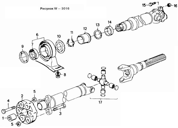
1 Guide bushing
2 Hinge disc
3 Bolt M10
4 Bolt M10
5 Self-locking nut
6 Middle support
7 Radial ball bearing
8 Bolt M8
9 Dust cover
10 Dust cover
11 Retaining ring
12 Threaded bushing
13 Toothed washer
14 Tension ring
15 Bolt M10
16 Self-locking nut M10
17 Crosspiece
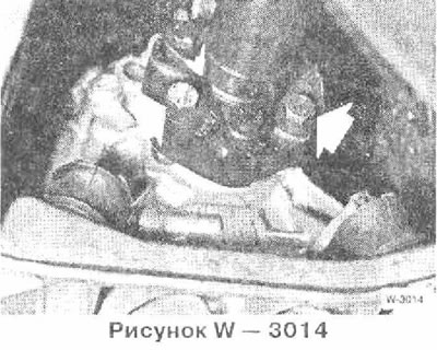
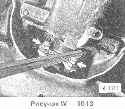
Using the BMW 261040 tool, loosen the threaded ring "arrow" a few turns. If you do not have this tool, loosen the threaded ring with a pipe wrench.
Unscrew the cardan shaft from the gearbox.
Vehicles with vibration damper: Remove the vibration damper from the gearbox. Turn the vibration damper 60° and attach it to the rubber coupling. The vibration damper is removed together with the propeller shaft.
Front crossbar design
Support the gearbox on a jack with a wooden block.
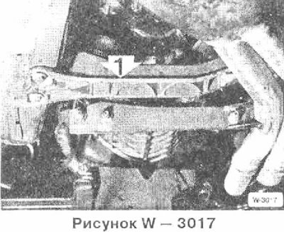
Remove the cross beam and gearbox mount.
Loosen the crosspiece nuts.
Remove the cardan shaft from the rear axle gearbox. Block the shaft with a crowbar.
Caution: On constant velocity joint designs, place the cap on the joint to protect it from dirt. Check for grease filling.
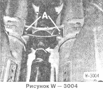
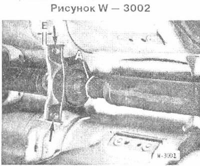
Remove the middle support A.
Bend the cardan shaft downwards and pull it out of the centering pin in the gearbox. If necessary, push the shaft completely into the movable joint.
Caution: Do not disconnect the cardan shaft at the sliding element.
Caution: Do not drop the cardan shaft. The rubber seal of the constant velocity joint may be damaged in particular.
Installation
If there are vibrations and noises, the cardan hall should be balanced in a workshop. In addition, the bending angle of the cardan shaft can be checked.
Note: The cardan shaft is balanced as a set and can only be replaced as an assembly. Replace worn cardan shafts.
Before installation, check the centering disk of the cardan shaft, if necessary, lubricate the disk with Moiykore Longtherm 2. Replace the damaged disk.
With the help of an assistant, push the cardan shaft into the centering pin of the gearbox.
Tighten the middle support with a tightening torque of 22 Nm. At the same time, shift the middle support with an interference fit of E = 4-6 mm in the direction of travel. Cardan shaft without sliding element: E = 2-4 mm.
Screw the cardan shaft to the rear axle gearbox. To avoid overtightening the cardan shaft, if possible, only the nuts or bolts on the flange side should be turned. Install new self-locking nuts with a tightening torque of 70 Nm.
Constant velocity joint design: Check seal, replace if necessary. Bolt propeller shaft to rear axle gearbox.
Tightening torques:
- m8 bolts - 32 Nm
- m10 bolts - 70 Nm
Vehicles with front crosspiece: Tighten new lock nuts to a tightening torque of 70 Nm.
Screw on the gearbox mount and cross beam, remove the jack.
On vehicles with vibration damper: Insert the vibration damper with a 60° rotation.
Screw the cardan shaft to the gearbox with new self-locking nuts.
Tightening torques:
- bolts M8-8.8 - 45 nm
- bolts M10-10.9 - 70 nm
- m12 bolts - 80 Nm
To avoid overtightening the cardan shaft, if possible only the nuts or bolts on the flange side should be turned. Block the cardan shaft from turning with a crowbar.
On vehicles with automatic transmission: Bolt the transmission mount.
Tighten the threaded ring to a torque of 17 Nm. If there is no special tool, tighten with a pipe wrench.
On vehicles without a sliding element: Tighten the fork to the support pin in the middle of the propeller shaft with a tightening torque of 110 Nm.
Screw on the catalytic converter heat shield.
Install the exhaust system.
Install the protective tray of the unit.
Lower the car.
[You can read the original on the website «BMWMAN.ru»]
This article is available at russian, bulgarian, belarusian, ukrainian, serbian, croatian, romanian, polish, slovak, hungarian
Article verified: Polikarpov Saveliy
Share information:
Previous articles
БМВ E34: Car gearbox
Next articles
Similar articles on other types of BMW cars:
Replacing the centering bearing with grooves of the primary shaft of… BMW 3 Series E21 (1975-1983)
Removal and installation the propeller shaft BMW 3 Series E30 (1982-1994)
Gearbox shaft bearings — replacement BMW 7 Series E32 (1986-1994)
Replacing the CV joint of the propeller shaft BMW 7 Series E38 (1994-2001)
Pressing out and pressing in the axle shaft into the flange (the axle… BMW X3 E83 (2003-2010)
Replacing the front propeller shaft BMW X5 E53 (1999-2006)
Link in different formats to this page
Visitor comments
No comments yet
- General information
- Governing bodies
- Manual
- Maintenance
- Power unit
- Engine repair
- Lubrication system
- Cooling system
- Ignition system
- Supply system
- Injection system (gasoline)
- Injection system (diesel)
- Exhaust system
- Transmission
- Clutch
- Car gearbox
- Front axle
- Rear axle
- Chassis
- Steering
- Brake system
- Wheels and tires
- Body
- Interior
- Exterior
- Heating system
- Electrical equipment
- Equipment and devices
- Power devices
- Windscreen wipers
- Electrical circuits
- General information
- Manual
- Maintenance
- Power unit
- Engine repair
- Ignition system
- Engine lubrication system
- Cooling system
- Fuel system (gasoline)
- Fuel system (diesel)
- Exhaust system
- Transmission
- Clutch
- Car gearbox
- Chassis
- Front and rear suspension
- Steering
- Brake system
- Body
- Exterior
- Interior
- Electrical equipment
- Heating system
- Equipment and devices
- Power devices
- Electrical circuits
- General information
- Manual
- Maintenance
- Power unit
- Engine in a car
- Engine overhaul
- Cooling system
- Supply system
- Ignition system
- Control system
- Transmission
- Clutch
- Manual gearbox
- Automatic gearbox
- Transmission line
- Chassis
- Steering
- Front suspension
- Rear suspension
- Brake system
- Body
- Body elements
- Car care and painting
- Electrical equipment
- Heater and air conditioner
- Equipment and devices
- Starter and generator
- Electrical circuits
- General information
- Operation and maintenance
- Specifications
- Power unit
- Engine repair
- Cooling and lubrication system
- Supply system
- Ecotronic power supply system
- Fuel injection system
- Ignition system
- Transmission
- Clutch
- Gearbox BMW 242/4
- Gearbox Getrag 262/8
- Gearbox Getrag 265/6
- Automatic gearbox
- Cardan gear
- Rear axle
- Chassis
- Steering
- Front suspension
- Rear suspension
- Brake system
- Electrical equipment
- Equipment and devices
- Electrical circuits