
The hydraulic brake drive system is divided into two circuits. As a result, if one brake circuit fails, for example due to a leak, the vehicle can be stopped by another circuit. The pressure in both brake circuits is created in the double brake master cylinder by the action of the brake pedal.
The brake force regulator on the rear axle is not needed, as the distribution of the brake force is carried out using ABS (anti-lock brake system).
The brake fluid reservoir is located in the engine compartment on the left side under the cabin air filter housing and provides the entire brake system with brake fluid.
The brake booster on gasoline engines uses part of the vacuum created in the intake manifold. Through the valve, the braking force from the pedal is amplified by the vacuum (rarefaction). Since the vacuum on a diesel engine is weak, the vacuum necessary for the operation of the brake booster (vacuum) generated by a vacuum pump mounted on a flange on the cylinder head.
Some models are equipped with a hydraulic brake booster with a regulator.
All disc brakes are equipped with so-called floating calipers (staples). This means that in each caliper, when braking, the brake pads are pressed against the brake disc by one piston.
The brake caliper is made of alloyed light alloy. Thanks to this, the parts of the brake system are light and provide good heat dissipation, which prevents the so-called FADING effect, which consists in reducing the effectiveness of the brakes due to heating of the brake pads and other brake parts.
The left front and right rear wheels each have one brake pad wear sensor.
Parking (manual) the brake is actuated by a cable and acts on the rear wheels. Since disc brakes are not very suitable as parking brakes, there are additionally two drum brakes on the rear wheels that are built into the brake discs. The drum brakes are only actuated with the parking brake lever.
When cleaning the brake system, dust from the work of the pads is removed. This dust is very harmful to health and should not be inhaled.
It is recommended to use brake pads certified by BMW and approved for use on the models described.
When working on the brake system, you must be perfectly clean and have experience working with brakes. If there is no such experience, then it is better to carry out these works in the workshop.
The brake fluid drained from the system must not be drained into the domestic sewer, only special containers should be used.
Attention: On wet roads, use the brakes from time to time to free the brake discs from deposits. While water is thrown off the brake discs by centrifugal force, they are left with a thin film of silicone, resin, grease and dirt that reduces braking performance.
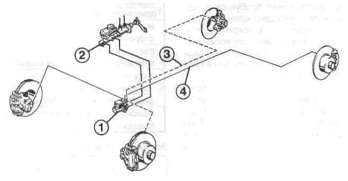
Elements of the brake system
1 - ABS hydraulic unit;
2 — the main brake cylinder;
3 and 4 - two circuits of the brake system.
ABS system
Anti-Lock Braking System (ABS) consists of an electro-hydraulic unit with an integrated electronic control unit, an ABS warning lamp and speed sensors with gears on all wheels.
ABS prevents the wheels from locking during heavy braking. Thanks to this, when braking, the car remains steerable. The operation of ABS is felt by the driver by the pulsations of the brake pedal and by the noise of the operation of the electro-hydraulic unit in the engine compartment.
A safety circuit in the electronic control unit ensures that the ABS in the event of a failure (e.g. due to a broken wire) or when the battery voltage drops (i.e. less than 10.5 V) turns off automatically, which is determined by the ignition of the ABS warning lamp on the instrument panel. In this case, the conventional braking system remains in operation. In this case, the car brakes as it would without the ABS system.
After switching on the ignition, the ABS system independently monitors for faults. After about 3 seconds, the ABS warning light on the instrument panel should go out. If the control lamp burns longer or in motion, then you need to do the following.
Stop for a short time, turn off the engine and start it again.
Check battery voltage. If it is less than 10.5 V, then charge the battery. Check whether the wire clamps on the AB contacts are tightly tightened and whether the contacts are reliable.
Raise and support the car, remove the wheels, check the electrical wires to the speed sensors for integrity. Other ABS checks should be done in a workshop that has special troubleshooting equipment.
Attention: Before carrying out electric welding, disconnect the plug from the ABS control unit with the ignition on. When carrying out painting work, the control unit must not be heated to a temperature of more than 85°C.
ASC+T system
ASC+T system (automatic stability and traction control) prevents slipping of the rear wheels (leading) wheels during acceleration, for example, on wet roads, when the spinning wheel transmits less traction. The system control unit is integrated into the ABS control unit.
The number of wheel revolutions is supplied to the control unit from the sensors on the wheels, which are used to operate the ABS system. If one of the rear wheels tends to spin, the DME control unit (digital engine electronics - engine management system) receives this information from the ABS/ASC+T control unit. The DME then reduces engine power by controlling the injectors and possibly influencing ignition timing. These adjustments act in the same way as they would if the driver released the pedal «gas». Engine power is reduced for a short time and the wheels regain their grip on the road. If this does not work, then the system comes into operation «T» (traction control), and it slows down the slipping drive wheels. Operation of the ASC + T system is determined by the flashing of the control lamp.
Engine torque control is built into the system. It prevents short-term blocking of the drive wheels on a slippery road due to the braking effect of the engine.
Up to 40 km/h the system «traction control» (T) may include differential lock. Since the left and right wheels brake independently of each other, the ASC+T system acts like a differential lock that is almost 100% engaged.
The ASC+T system recognizes faults that occur on its own. After switching on the ignition, the control lamp lights up for a short time and then goes out.
If the lamp does not go out or lights up while driving, this indicates a malfunction. The vehicle can then move on, but the ASC+T system will not work. When driving with snow chains, in deep snow or when driving out of mud, it is recommended to deactivate the ASC+T system using the switch in the center console. When the system is turned on again using the switch or the next time the engine is started, the system will be turned on again.
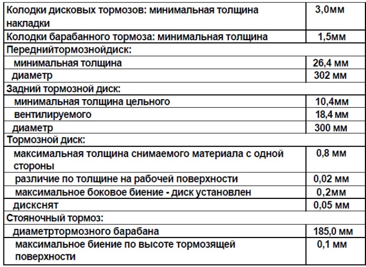
Brake system technical data
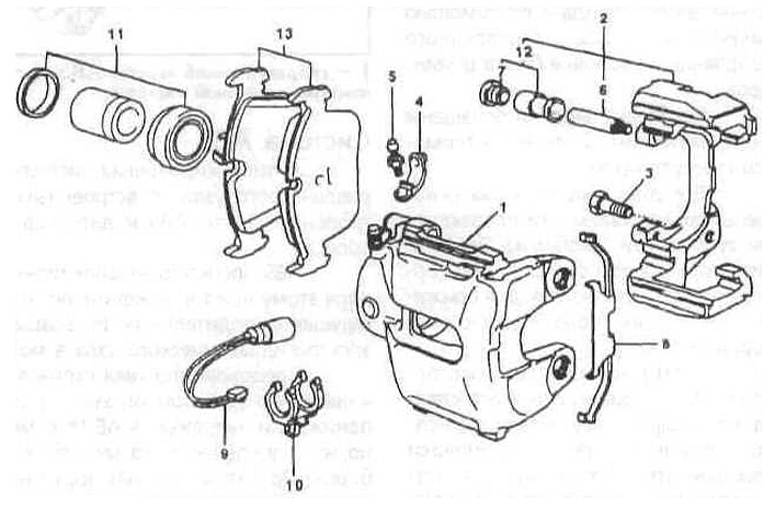
Elements of the front brake caliper
1 - brake caliper;
2 - mount (brace);
3 - bolt, tightening torque 11 Nm;
4 - dust cap;
5 - valve for air removal;
6 - guide bolt;
7 - protective cap;
8 - fastening spring;
9 - wear sensor;
10 - brake pad wear sensor holder;
11 - a set of caliper cuffs;
12 - repair kit guide sleeve;
13 - brake pads (asbestos-free).