



- Home
- BMW 7 Series
- E32
- Power unit
- Lubrication system
- Oil pump — removal, installation and inspection
Oil pump — removal, installation and inspection (BMW 7 Series E32)
Oil pump of the M52 series engine - removal and installation
Removal
Note: To check the operation of the pressure reducing valve, it is sufficient to remove the oil pan. The oil pump does not need to be removed.
Remove the oil pump. Unscrew the nut, remove the oil pump sprocket together with the chain. At the same time, release the chain tensioner (press it).
Note: The nut has a left-hand thread, so to unscrew it you need to turn it to the right.
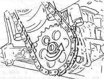
Loosen the oil pump mounting bolts (arrows) and remove the oil pump. Note the position of the two guide bushings on the cylinder block.
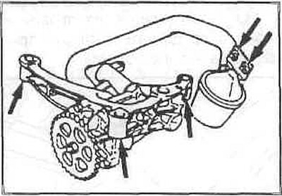
Pull the oil pump back and remove it.
Examination
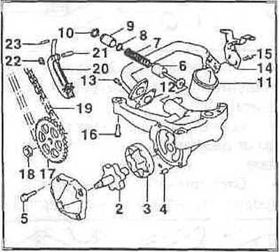
If necessary, disassemble and clean the oil pump in the following order: unscrew the bolts (13) and remove the oil intake, unscrew the bolts (5) of the pump body. Do not lose the guide bushings (4).
Check rotors (2) and (3) for wear and damage, replace if necessary.
Technical data
The radial clearance between the outer rotor and the pump body is 0.18 mm.
Axial clearance of the inner rotor is no more than 0.08 mm; outer rotor - no more than 0.09 mm.
Remove the retaining ring (10) and take out the pressure reducing valve. Check the length of the unloaded spring, replace it if necessary. The length of the spring should be 84.1 mm.
Caution: The sealing ring (8) must always be replaced. Carefully insert the pressure reducing valve, install the retaining ring.
Install the oil pickup with a new gasket, the protrusion on the gasket should be directed towards the oil pickup screen.
Lubricate all parts with engine oil, install the oil pump cover and tighten its bolts to a torque of 10 Nm.
Installation
Insert the oil pump, tighten its mounting bolts to 20 Nm. There should be two centering bushings between the cylinder block and the oil pump housing. Install the sprocket with the chain and tighten the left-hand thread nut to 25 Nm. If removed, install the chain tensioner.
Install the oil pan.
Oil pump of the M30 series engine - removal and installation
The oil pump is located at the bottom of the oil pan and is attached to the engine block. The pump is driven by a single-row roller chain. To adjust the chain tension, plates can be inserted between the engine block and the pump.
The pressure reducing valve is mounted directly on the pump body.
Note: To remove the pump, you must remove the oil pan.
Removal
Raise the car and drain the oil.
Remove the underbody protection.
Disconnect the ground cable from the battery.
Remove the generator.
Remove the water pump, leaving the wires connected.
Unscrew and remove the oil pan forward. Turn the crankshaft accordingly.
Unscrew the chain sprocket from the oil pump and remove it from the chain. Carefully remove the pads. Remove the pressure reducing valve by unscrewing the mounting bolt.
Unscrew the pump cover. Remove the outer rotor. Wash all parts.
Examination
Visually inspect the pump parts for wear.
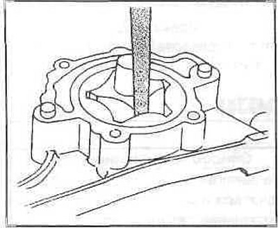
Install the outer rotor and check the rotor clearance.
Required clearances
- Axial clearance rotor-pump body: 0.04-0.1 mm.
- Gap outer-inner rotor: 0.12-0.20 mm.
If these clearances are exceeded or there are pits on the parts, the pump must be replaced as a set. The length of the pressure reducing valve spring should be 68 mm, a shorter spring must be replaced.
Installation
The pump is installed in the reverse order, taking into account the following:
Once the pump is bolted to the engine block, check for ease of movement of the pump (the chain drive is not installed yet). If it sticks, the pump body is warped. The old pump should be replaced.
Check the flatness of the mounting surface of the new pump. The adjusting plate must be replaced. Select the adjusting plate so that the chain has a play of 3-5 mm on the branch.
The chain must not be overtightened under any circumstances.
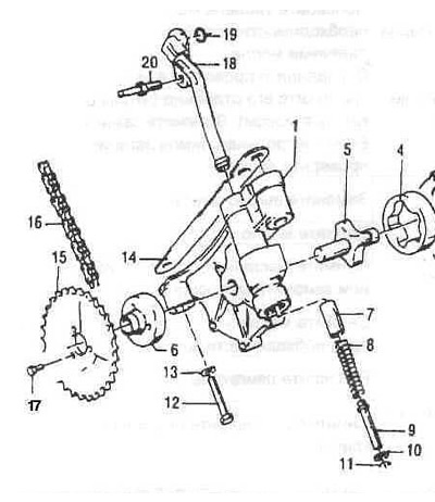
Oil pump components of the M30 series engine
1 — oil pump housing;
2 - lid;
3 - metal gasket;
4 — outer rotor;
5 - internal rotor;
6 — hub;
7 — piston;
8 - pressure spring;
9 - guide tube;
10 - safety ring;
11 - spring washer;
12 - Hex bolt;
13 - spring washer;
14 - spacer (available in 0.1mm and 0.6mm thickness);
15 - asterisk;
16 — chain;
17 - Hex bolt;
18 — discharge pipeline;
19 — O-ring;
20 - mounting pin;
21 - Hex bolt;
22 - spring washer.
Oil pump of the M70 series engine - removal and installation
The lubrication system consists of a suction and pressure pump in the oil pan with a pressure reducing valve, an oil filter with a thermostat valve and an oil radiator located above the water radiator.
The pump is driven from the crankshaft via a roller chain.
The rear part of the pump sucks oil from the crankcase and transfers it forward to the delivery pump. Thanks to this, the engine receives non-foamed oil, which is absolutely necessary for the perfect operation of hydraulic tappets.
The pressure reducing valve limits the maximum oil pressure.
At very low temperatures the valve opens at oil pressure above 10 bar.
Starting at an oil temperature of 95°C, the thermostat valve in the filter housing allows oil to flow through the oil cooler.
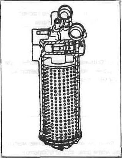
The oil pump can be accessed from below after unscrewing the oil pan.
Removal
Attention: The installation sequence given must be followed.
Loosen the chain sprocket mounting nuts and remove the sprocket with the chain.
Unscrew the oil line from the rear to the oil pan.
Remove the three mounting bolts. Remove the pump.
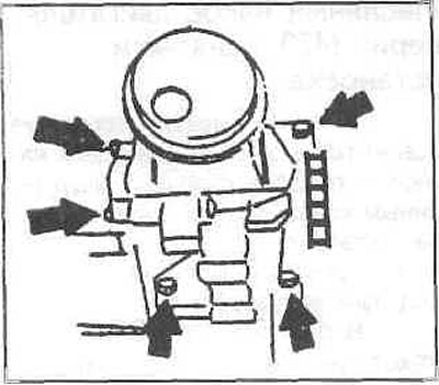
Unscrew the back cover and remove the rotors. Remove the inner rotor wedge from the shaft.
Loosen the front cover and remove the rotors together with the shaft.
The front inner rotor is pressed onto the shaft and should not separate from it.
If wear is visible, replace the pump as a set.
Screw in the plunger of the pressure reducing valve and remove the retaining ring with a collet.
Remove the plunger with the spring.
Examination
Degrease all parts. Insert the outer rotors into the housing and measure the radial and axial clearances with a flat feeler gauge.
- Axial clearance: 0.04-0.09 mm.
- Radial clearance: 0.12-0.20 mm.
To measure axial clearance, place a ground straightedge on the mating surface.
Repeat the measurement with the inner rotor. The axial clearance can be 0.02-0.065 mm.
The plunger of the pressure reducing valve should slide easily in the hole.
The inner rotor of the rear suction pump must fit onto the shaft with a wedge without any clearance.
If there is a very large gap or visible wear, the pump assembly should be replaced.
Installation
The pump is installed in the reverse order of removal.
This article is based on data from the website: «BMWman»
This article is available at russian, bulgarian, belarusian, ukrainian, serbian, croatian, romanian, polish, slovak, hungarian
Article verified: Sevastyanov Nikolay
Share information:
Previous articles
БМВ E32: Lubrication system
Next articles
Similar articles on other types of BMW cars:
Oil pump — removal, inspection and installation BMW 3 Series E46 (1998-2006, petrol)
Mechanical fuel pump — checking, adjustment, removal and installation BMW 3 Series E21 (1975-1983)
Removal, inspection and installation of the oil pump BMW 5 Series E28 (1981-1988)
Removal and installation the oil pump BMW 5 Series E12 (1972-1981)
Pistons — removal and installation BMW X3 E83 (2003-2010)
Removal and installation the engine BMW X5 E53 (1999-2006)
Oil pump — removal, inspection and installation BMW 3 Series E46 (1998-2006, petrol)
Mechanical fuel pump — checking, adjustment, removal and installation BMW 3 Series E21 (1975-1983)
Removal, inspection and installation of the oil pump BMW 5 Series E28 (1981-1988)
Removal and installation the oil pump BMW 5 Series E12 (1972-1981)
Pistons — removal and installation BMW X3 E83 (2003-2010)
Removal and installation the engine BMW X5 E53 (1999-2006)
Link in different formats to this page
Visitor comments
No comments yet
- General information
- Introduction to guide
- Manual
- Maintenance
- Power unit
- Engine M60/1, M60/2 (petrol)
- M62 engine (petrol)
- M57 engine (diesel)
- M67 engine (diesel)
- Cooling system
- Fuel system (petrol)
- Fuel system (diesel)
- Exhaust system
- Ignition and control systems
- Charge and launch systems
- Transmission
- Clutch
- Mechanical gearbox
- Automatic gearbox
- Cardan and drive shafts
- Chassis
- Brake system
- Front suspension
- Rear suspension
- Steering
- Body
- Exterior
- Interior
- Electrical equipment
- Equipment and devices
- Lighting
- Heating and air conditioning
- Electrical circuits
- General information
- Care and maintenance
- Power unit
- Minor engine repair
- Engine overhaul
- Lubrication system
- Cooling system
- Ignition system
- Supply system
- Injection system (petrol)
- Injection system (diesel)
- Exhaust system
- Transmission
- Clutch
- Manual gearbox
- Automatic gearbox
- Cardan gear
- Rear axle and shafts
- Chassis
- Front suspension
- Rear suspension
- Steering
- Wheels and tires
- Brake system
- Body
- Body elements
- Electrical equipment
- Equipment and devices
- Electrical circuits