
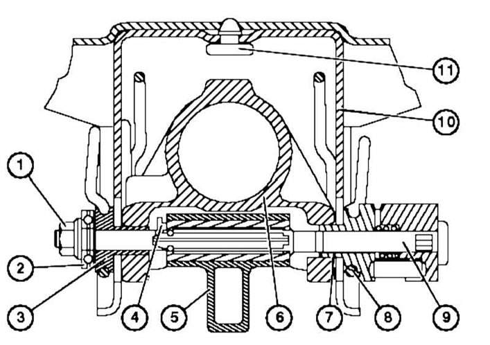
Steering column adjustment lever design
1 - Nut
2 - Bearing
3 - Clamping disc
4 — Retainer
5 - Lever
8 — Torsion spring
9 — Clamping device
1. Remove the upper and lower steering column covers (see section Removal and installation steering column covers).
2. Remove the wood panel and the trim panel of the glove box on the left.
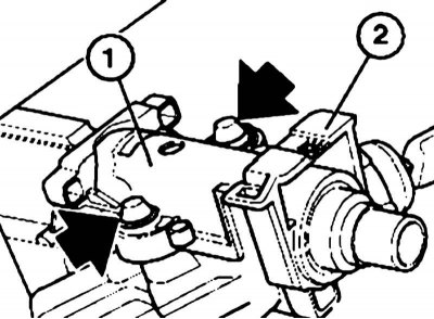
3. Release the torsion spring (8) on both sides, loosen the nut (1) and remove the thrust bearing (2), clamping disc (3) and retainer (4).
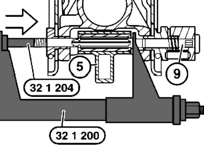
4. Using special tool No.32 1 200 and nozzle No.32 1 204, press out the clamping device (9) from the steering column adjustment lever (5). Hold the device by the flats with a wrench.
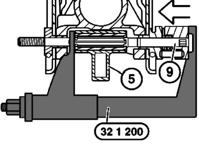
5. The adjustment lever should point towards the steering column shaft lock, and the square head of the clamping device should be inserted into the hole in the steering shaft mounting bracket pipe.
6. Press the clamping device (9) into the steering column adjustment lever (5) using special tool No.32 1 200. Put on the retainer (4), clamping disk (3) and thrust bearing (2). Insert the torsion spring (8) on both sides.
Replace the nut (1).
[This article is based on data from the website: BMWman.ru]