
Bipod
When replacing the steering arm, check the height of its installation in relation to the pendulum arm.
1. Remove the steering gear (see Section Removal and installation of the steering gear with power steering).
2. Loosen the clamping screw (1), having previously noted the position of the adjustable steering bipod on the shaft with a gear sector.
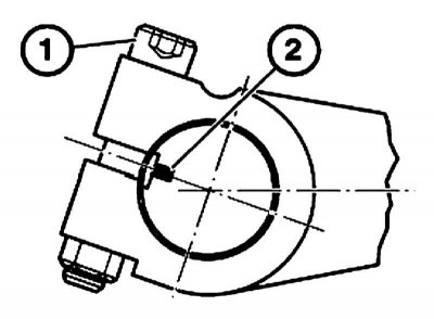
1 - Clamping screw
2 - Labels
3. Installation is carried out in the reverse order. Fit the steering arm to the marked mark. At the same time, the label (2) should be in the middle of the steering arm slot.
Replace self-locking nut. Tie rods
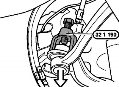
1. Loosen the nut and remove the tie rod using tool no. 32 1 190.
When installed on the trunnion and in the hole, there should be no traces of grease. Replace self-locking nut. If necessary, hold the assembly from turning by the internal hexagon.
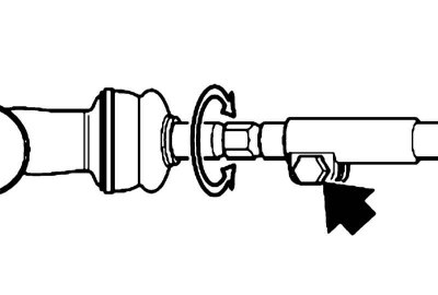
2. Loosen the clamping bolt and unscrew the tie rod.
3. Installation is carried out in the reverse order. Lubricate the traction control sleeve completely with special grease.
4. Upon completion of work, check and adjust the angles of the front wheels.
Medium thrust
1. Remove the engine crankcase protection.
2. Give a nut and disconnect draft from a bipod of a steering and from the pendulum lever by means of a puller No. 32 1 190.
When installing, replace the self-locking nut. If necessary, hold the assembly from turning by the internal hexagon.
3. Loosen the left and right clamp bolts (see illustration) and turn out the draft adjusting sleeve on the left and right.
4. Measure the installation depth of the adjusting sleeve at the ends of the old rod and screw the adjusting sleeve on the new rod to the appropriate depth on both sides.
5. Installation is carried out in the reverse order. Lubricate the traction control sleeve with special grease.
6. Upon completion of work, check and adjust the angles of the front wheels.
Pendulum lever
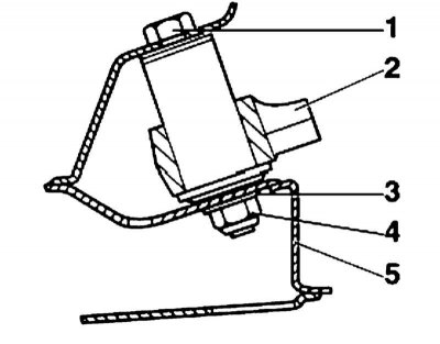
Details of the attachment point of the pendulum arm
1 - Bolt
2 - Pendulum lever
3, 4 - Self-locking nut
5 - Front axle beam
After replacing the pendulum arm, the steering arm must be adjusted.
1. Remove the engine crankcase protection.
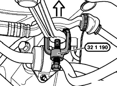
2. Give a nut and disconnect a spherical support by means of a puller No. 32 1 190.
When installed on the trunnion and in the hole, there should be no traces of grease. Replace self-locking nut. If necessary, hold the assembly from turning by the internal hexagon.