
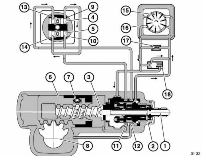
Design and operating principle of the power steering
1 — Shaft
2 — Torsion
3 - Screw
4, 5 - Spools
6 — Piston
7 - Circulation tube
8 — Shaft with toothed sector
9, 10 — Inlet valves
11, 12 - Radial channels
13, 14 — Exhaust valves
15 — Pump
16 — Reservoir
17 — Safety valve
18 — Regulating valve
The steering gear housing contains the steering gear assembly, the control spool valve and the working cylinder. The steering shaft (1) is elastically connected to the screw (3) and rigidly to the spool valves (4 and 5) via the torsion bar (2). The spool valves are built into the distributor housing in a transverse position relative to the screw axis. The connection between the piston (6) and the screw (3) is achieved via a closed ball chain. When the screw is turned, the circulation tube (7) takes the balls from one end of the chain and moves them to the other end. The piston (6) is connected via a toothed engagement to the shaft (8), which has a toothed sector. The special tooth profile of the shaft sector makes it possible to eliminate play using the adjusting screw. In the neutral position of the spool valves (4 and 5), the oil supplied by the pump circulates in the steering mechanism and has free access to the cylinder through the open inlet and outlet control edges. The hydraulic drive comes into operation when the spools leave the neutral position. This happens when the force from the steering wheel or from the steering knuckle is transmitted to the screw through the shaft with the toothed sector and the piston. In this case, the torsion (2) acts as a connecting element. Its flexible part has the ability to deform and return the spools to the neutral position after the force from the steering wheel is removed. When the spools leave the neutral position, oil is also directed to the working cylinder - this provides force support in the movement of the steering shaft and counteraction during impacts caused by unevenness of the road. Steering wheel in neutral position: from the vane pump, oil flows into the distributor housing, through the inlet channels (9 and 10) to the radial channels (11 and 12). From there it flows further through the connecting holes to the right and left cavities of the cylinder, and then through the open outlet channels (13 and 14) back to the reservoir. The steering wheel is turned clockwise/counterclockwise: The spool (4/5) moves to the right and the inlet port (9/10) opens. The spool (5/4) moves to the left and the inlet port (10/9) closes. Thus, oil enters the right/left cylinder cavity, is pushed out of the left/right cylinder cavity and returns to the reservoir.
Original publication posted on the website «BMWMAN»