The oil pump must be removed in the following order.
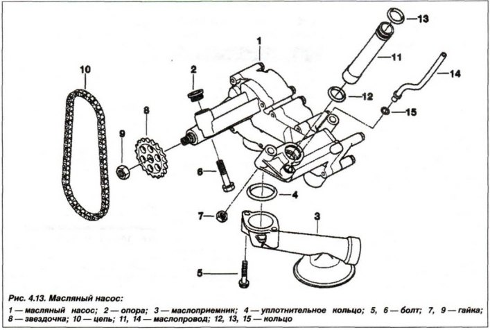
Remove the upper part of the engine oil pan, unscrew the M10x1.0 nut (9) and remove the oil pump drive sprocket (8) together with the drive chain (10).
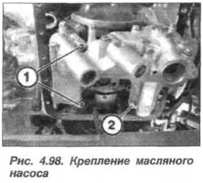
Loosen the bolt (2, Fig. 4.98) and nuts (1) securing the oil pump and remove it.
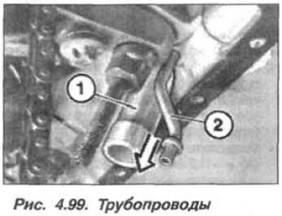
Remove the intake pipe (1, Fig. 4.99) unfiltered oil and a pressure line (2) of filtered oil from the engine cylinder block.
Caution! The pressure reducing valve spring is heavily compressed.
The design of a pressure reducing valve with a temperature-controlled piston is shown in Figure 4.100.
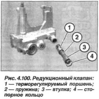
If necessary, remove the piston of the pressure reducing valve by pressing on the sleeve with a suitable rod (3, Fig. 4.100) inside and remove the retaining ring (4).
The installation of the oil pump must be carried out in the following order.
Attention! When performing further operations, avoid damaging the seal edges against the edges of the cylinder block housing.
Replace the sealing rings (12, 13, see Fig. 4.13) round cross-section on the intake pipe, lightly lubricate them with engine oil and insert the intake pipe into the cylinder block.
Replace the sealing ring (15, see Fig. 4.13) round section on the pressure pipe and lightly lubricate it with engine oil.
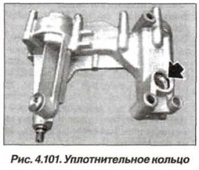
Insert the pressure pipe into the engine block in a position that ensures its fixation in the oil pump after installing the pump on the engine. Replace the sealing ring (arrow, Fig. 4.101) oil pump.
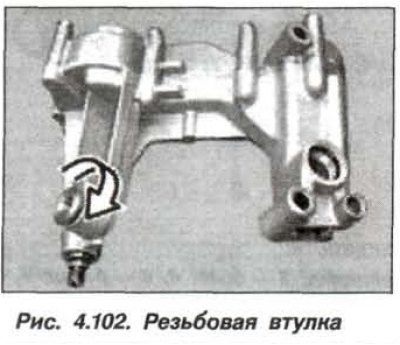
Screw the threaded sleeve into the oil pump housing until it stops (arrow, Fig. 4.102).
Align the oil supply intake pipe and the pressure pipe so that they match the corresponding holes in the oil pump. Slide the oil pump onto the pipes.
Install and tighten the nut (7, see Fig. 4.13) fastening the oil pump with a torque of 20 Nm (2.0 kgf·m).
Install the sprocket (8) with the chain (10) on the pump shaft and tighten the nut (9, M10) securing the oil pump drive sprocket to a torque of 45 N·m (4.5 kgf·m).
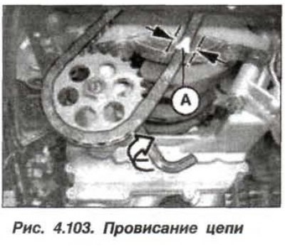
Turning with a socket wrench (arrow, Fig. 4.103) threaded sleeve in the pump, adjust the chain tension so that the maximum chain sag (A) is 2.0 mm.
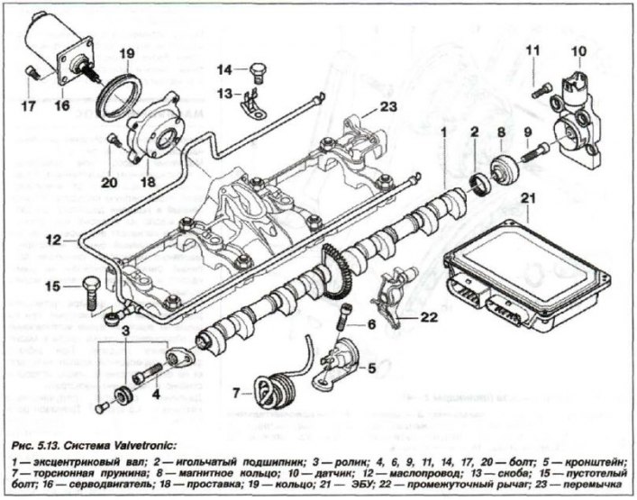
Insert and tighten the new self-locking bolt (6, see fig. 5.13, M8x45) oil pump mounts.