



- Home
- BMW 3 Series
- E36
- Power unit
- Engine repair
- Removal and installation the engine
Removal and installation the engine (BMW 3 Series E36)
Before removing the engine, the gearbox must be removed. The engine is removed without the gearbox upwards. The intake and exhaust manifolds, as well as the generator, remain on the engine. A crane is required to remove the engine.
Since some connections underneath the car also need to be removed, the car needs to be lifted and placed on reliable stands. The front fenders need to be covered before installation work in the engine compartment.
Electrical wires, as well as vacuum and water hoses, may be routed differently in the engine compartment depending on the year of manufacture and the composition of the equipment. Since it is impossible to provide a detailed description of each of the routing options, I recommend labeling the wires and hoses when disconnecting them.
Description of engine removal on models 316i, 318i (4 and also on models 3201,325t (6-cylinder engines). The engines installed on the 316i and 318i models from September 1993 have changes associated with a new ignition system without a distributor and a modified intake manifold.
Remove the gearbox.
Raise the car.
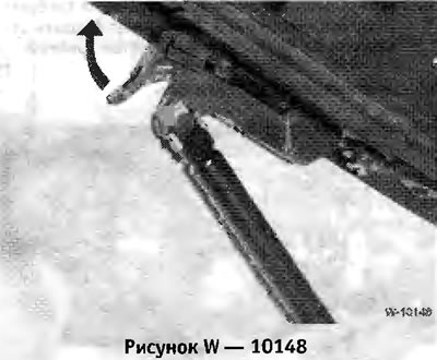
Install the engine compartment hood in the installation position, i.e. vertically. To do this, disconnect the hook "arrow" and press the hood upward. Press the hinge hinge and release the hood.
Disconnect the ground wire from the battery.
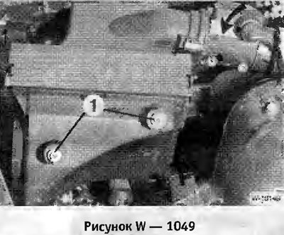
Remove the air filter and air flow meter. To do this, turn the knurled nut on the connector to the left and remove the connector. Unscrew the bolts "1" and release the clamp on the hose and pull out the air filter box.
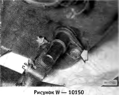
Six-cylinder engine: Unscrew the cooling system/intake air thermostat and pull out the sensor
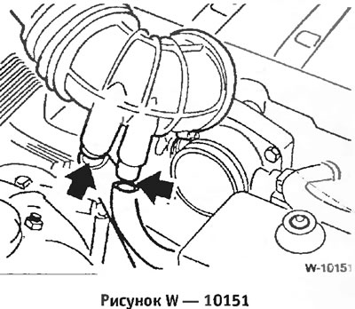
Disconnect the idle air control valve and PCV hoses from the intake hose. Four-cylinder engine: Remove the electrical wire fasteners from the intake hose.
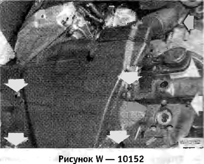
Six-cylinder engine: Unscrew the air duct of the "arrow" generator and pull it out.
Drain the coolant.
Remove the radiator.
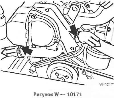
Disconnect the water hoses from the thermostat housing, having first released the hose clamps.
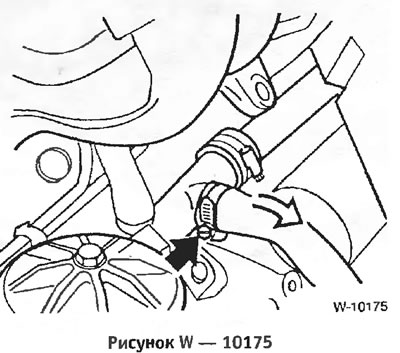
Disconnect the hose from the engine that goes to the expansion tank of the cooling system.
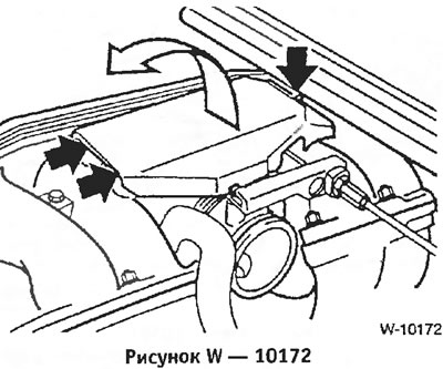
Remove the throttle lever cover. To do this, unscrew the bolt, lift the cover and unscrew the 2 front bolts.
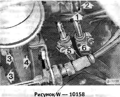
Disconnect the gas cable "1" by releasing the clamp in the direction of the arrow. If there is an automatic transmission, also disconnect the cable "2".
Unscrew bolts "3" and put the cables with fasteners aside.
Disconnect the idle speed control valve connector "4" and vacuum hoses "5" and "6".
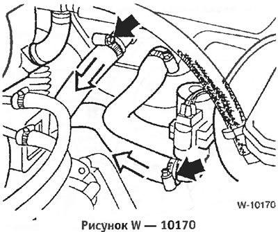
Disconnect the water hoses from the heater tap and from the heater, having first released the clamps.
Remove the heater fresh air intake duct.
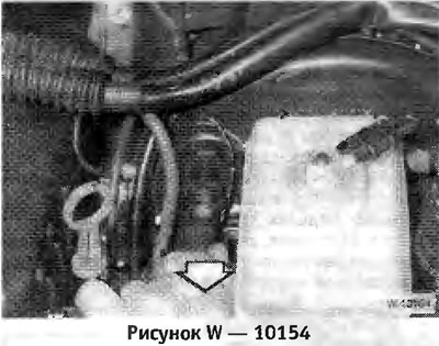
Disconnect the vacuum hose from the brake booster. Removal requires force.
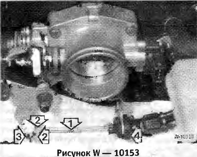
Disconnect the gas cable "1" from the throttle lever. To do this, press the throttle lever in the direction of the cable, release the nipple "3" with a narrow screwdriver. Squeeze the tabs "2" of the clamp and pull it out of the throttle lever. Pull the gas cable down from the slot in the throttle lever. If present, remove the second cable in the same way (with a special composition of the speed control system equipment, see figure).
Remove the oil filler cap.
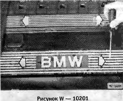
Use a screwdriver to pry up the small "arrow" plugs and unscrew the bolts located underneath. Remove 2 plastic covers from the cylinder head.
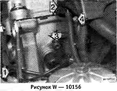
Unscrew the ground jumper "1" from the front side of the cylinder head.
Disconnect the ventilation nipple "2" of the cylinder head, while lifting the bar on the nipple with a screwdriver.
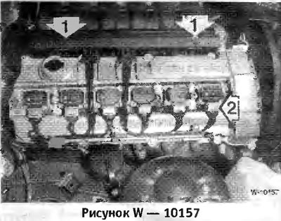
Unscrew 2 bolts -1 and pull the connector block upwards. Note the position of the rubber gaskets for subsequent installation.
On each ignition coil, pull up the metal bracket "2" and disconnect the connector, see the figure. Remove the connector block together with the wires.
Disconnect the following hoses and connectors from the throttle valve pipe. It is advisable to mark the hoses and wires and their connection points before disconnecting, so as not to mix them up during subsequent installation. Release the hose clamps, squeeze the connector locking clips. "1" throttle switch connector, "2" air temperature sensor connector, "3" throttle valve heating water hoses, "4" fuel tank ventilation hose, "6" fuel supply hose (white nipple), "7" return fuel hose (black nipple).
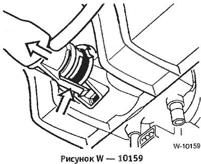
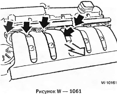
Six-cylinder engine: Disconnect the idle air control valve hose from the bottom of the intake manifold. Caution: The retaining tabs are easily broken. The connection point is not visible from above, the figure shows the view of the intake manifold from below.
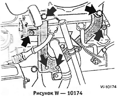
Four-cylinder engine
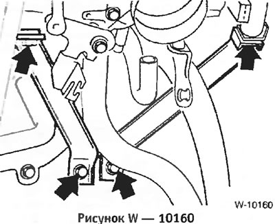
Six-cylinder engine
Unscrew the intake pipe support.
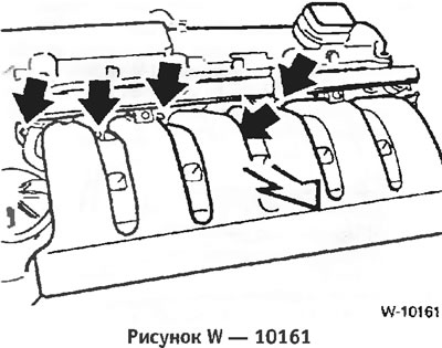
Unscrew the intake manifold from the cylinder head.
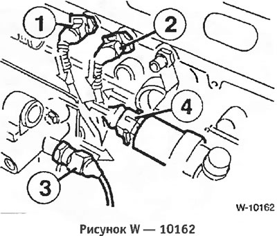
While pressing the wire clamps, disconnect the connectors. "1" temperature sensor, "2" temperature gauge sensor, "3" oil pressure switch, "4" idle speed control valve.
— On a four-cylinder engine, additionally disconnect the following connectors: ignition wires from the ignition coil, injector connectors (at the end of the cable channel), fuel tank ventilation valve detachable connection (in the wire between the activated carbon tank and the inlet pipe).
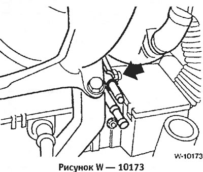
Four-cylinder engine: Loosen the fuel hose bracket.
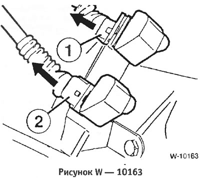
Disconnect the connectors on the flywheel housing: "1" cylinder identification sensor (black); "2" DME pulse sensor (Motronic, grey).
Disconnect the generator and starter wires.
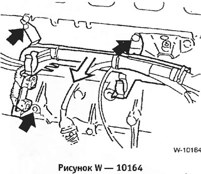
Unscrew the cable channel from the engine block and set the engine wiring harness aside.
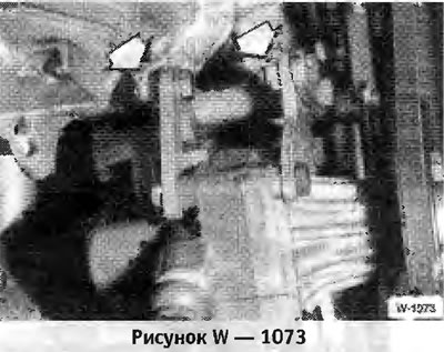
Four-cylinder engine
Six-cylinder engine
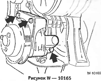
Vehicles with power steering: Remove the V-belt, unscrew the power steering pump and set it aside with the hoses connected.
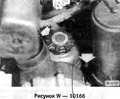
Unscrew the 2 bolts securing the power steering reservoir to the left engine support beam and hang the reservoir on a wire.
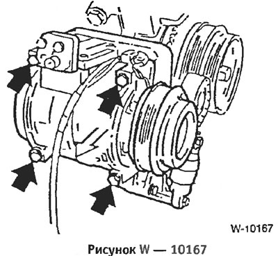
Vehicles equipped with air conditioning: Unscrew the air conditioning compressor and set it aside with the hoses connected. Caution: Never open the air conditioning circuit, as the freon leak may cause frostbite.
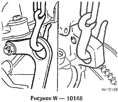
Hook the engine with a cable. To do this, connect the cable or chain to the engine's "arrow" lifting eyes. Raise the engine slightly with a crane.
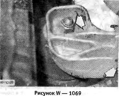
Unscrew the nuts from the right engine support and also the ground jumpers - arrows.
In the same way, unscrew the nuts from the left engine support.
Check that all hoses and wires connecting the engine to the body are disconnected, and then remove the engine
The removed engine cannot stand for more than 10 minutes in an inverted position, since the hydraulic valve clearance compensators will become empty and will become inoperative. If it is necessary to turn the engine over, remove the hydraulic valve clearance compensators.
Check the engine mounts, water, oil and fuel hoses for breaks or cracks and replace them if necessary.
Check the ease of rotation of the crankshaft bearing and clutch release bearing and the ease of movement of the clutch release fork.
Check the thickness and condition of the friction lining of the driven clutch disc.
Carefully insert the engine into the engine compartment. To avoid damage to the drive shaft, clutch and body, lower the engine very carefully.
Screw on the engine mount nuts without tightening them.
Raise the car.
Install the gearbox.
Lower the car.
Pull the engine to align it. Then tighten the engine mounts to 45 Nm.
If removed, install the air conditioning compressor.
Tighten the power steering pump.
Install and tension the V-belt.
Connect the connectors of the cylinder identification sensor and the DME pulse sensor on the flywheel housing. Connect the connectors of the temperature sensor, temperature gauge sensor, oil pressure switch and idle speed control valve.
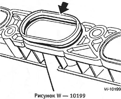
Six-cylinder engine: Insert the intake pipe into the cylinder head and screw it on. Replace all gaskets "arrows" before installation.
Screw on the intake pipe support.
Connect all electrical wires, vacuum, water and fuel hoses to the throttle valve fitting and to the cylinder head in accordance with the markings made during removal. Secure the hoses with clamps. Secure the electrical wires with cable clamps.
Place and screw the connector block onto the cylinder head.
Install and screw on the cylinder head trim.
Connect all removed connectors and hoses. Secure the hoses with clamps
Connect the throttle cable and, if available, the automatic transmission cable.
Connect the vacuum hose to the brake booster.
Insert and screw in the heater fresh air supply duct.
Attach electrical wires to the generator.
Screw on the generator cover.
Check the air filter element, knock it out or replace it if necessary. Install the air filter.
Connect and secure the heater water hoses with clamps.
Install the radiator.
Install the fan.
Check the frost protection properties of the coolant and add concentrate if necessary.
Check the oil level in the engine and gearbox and top up if necessary.
Connect the wires to the battery.
Start the engine and warm it up to operating temperature, check the coolant level and the tightness of all hose connections.
Install the powertrain protective tray.
Since some connections underneath the car also need to be removed, the car needs to be lifted and placed on reliable stands. The front fenders need to be covered before installation work in the engine compartment.
Electrical wires, as well as vacuum and water hoses, may be routed differently in the engine compartment depending on the year of manufacture and the composition of the equipment. Since it is impossible to provide a detailed description of each of the routing options, I recommend labeling the wires and hoses when disconnecting them.
Description of engine removal on models 316i, 318i (4 and also on models 3201,325t (6-cylinder engines). The engines installed on the 316i and 318i models from September 1993 have changes associated with a new ignition system without a distributor and a modified intake manifold.
Removal
Remove the gearbox.
Raise the car.
Install the engine compartment hood in the installation position, i.e. vertically. To do this, disconnect the hook "arrow" and press the hood upward. Press the hinge hinge and release the hood.
Caution: When the engine compartment hood is installed in the installation position, it is prohibited to turn on the windshield wiper. The windshield wiper does not have freedom of movement and scratches the hood. It is recommended to remove the windshield wiper fuse.
Disconnect the ground wire from the battery.
Caution: When the battery is disconnected, the information in the electronic memory devices, such as the engine fault memory or the radio security code memory, is erased. When disconnecting the battery, follow the instructions in the sections "Radio" and "Removing and installing the battery".
Note: On vehicles with six-cylinder engines, the battery is located in the luggage compartment next to the spare tire.
Remove the air filter and air flow meter. To do this, turn the knurled nut on the connector to the left and remove the connector. Unscrew the bolts "1" and release the clamp on the hose and pull out the air filter box.
Six-cylinder engine: Unscrew the cooling system/intake air thermostat and pull out the sensor
Disconnect the idle air control valve and PCV hoses from the intake hose. Four-cylinder engine: Remove the electrical wire fasteners from the intake hose.
Six-cylinder engine: Unscrew the air duct of the "arrow" generator and pull it out.
Drain the coolant.
Remove the radiator.
Note: If the hoses are secured with clamps, cut them and install screw clamps during installation.
Four-cylinder engine
Disconnect the water hoses from the thermostat housing, having first released the hose clamps.
Disconnect the hose from the engine that goes to the expansion tank of the cooling system.
Remove the throttle lever cover. To do this, unscrew the bolt, lift the cover and unscrew the 2 front bolts.
Disconnect the gas cable "1" by releasing the clamp in the direction of the arrow. If there is an automatic transmission, also disconnect the cable "2".
Unscrew bolts "3" and put the cables with fasteners aside.
Disconnect the idle speed control valve connector "4" and vacuum hoses "5" and "6".
Disconnect the water hoses from the heater tap and from the heater, having first released the clamps.
Remove the heater fresh air intake duct.
Disconnect the vacuum hose from the brake booster. Removal requires force.
Caution: Cover the hole on the power steering with a clean cloth.
Six-cylinder engine
Disconnect the gas cable "1" from the throttle lever. To do this, press the throttle lever in the direction of the cable, release the nipple "3" with a narrow screwdriver. Squeeze the tabs "2" of the clamp and pull it out of the throttle lever. Pull the gas cable down from the slot in the throttle lever. If present, remove the second cable in the same way (with a special composition of the speed control system equipment, see figure).
Remove the oil filler cap.
Use a screwdriver to pry up the small "arrow" plugs and unscrew the bolts located underneath. Remove 2 plastic covers from the cylinder head.
Unscrew the ground jumper "1" from the front side of the cylinder head.
Disconnect the ventilation nipple "2" of the cylinder head, while lifting the bar on the nipple with a screwdriver.
Unscrew 2 bolts -1 and pull the connector block upwards. Note the position of the rubber gaskets for subsequent installation.
On each ignition coil, pull up the metal bracket "2" and disconnect the connector, see the figure. Remove the connector block together with the wires.
Disconnect the following hoses and connectors from the throttle valve pipe. It is advisable to mark the hoses and wires and their connection points before disconnecting, so as not to mix them up during subsequent installation. Release the hose clamps, squeeze the connector locking clips. "1" throttle switch connector, "2" air temperature sensor connector, "3" throttle valve heating water hoses, "4" fuel tank ventilation hose, "6" fuel supply hose (white nipple), "7" return fuel hose (black nipple).
Warning: Fire hazard, no smoking. Wipe up any spilled fuel with a cloth.
Six-cylinder engine: Disconnect the idle air control valve hose from the bottom of the intake manifold. Caution: The retaining tabs are easily broken. The connection point is not visible from above, the figure shows the view of the intake manifold from below.
Four-cylinder engine
Six-cylinder engine
Unscrew the intake pipe support.
Unscrew the intake manifold from the cylinder head.
Caution: Do not allow any objects to enter the intake duct. Failure to remove objects may cause severe engine damage.
While pressing the wire clamps, disconnect the connectors. "1" temperature sensor, "2" temperature gauge sensor, "3" oil pressure switch, "4" idle speed control valve.
— On a four-cylinder engine, additionally disconnect the following connectors: ignition wires from the ignition coil, injector connectors (at the end of the cable channel), fuel tank ventilation valve detachable connection (in the wire between the activated carbon tank and the inlet pipe).
Four-cylinder engine: Loosen the fuel hose bracket.
Disconnect the connectors on the flywheel housing: "1" cylinder identification sensor (black); "2" DME pulse sensor (Motronic, grey).
Disconnect the generator and starter wires.
Unscrew the cable channel from the engine block and set the engine wiring harness aside.
Four-cylinder engine
Six-cylinder engine
Vehicles with power steering: Remove the V-belt, unscrew the power steering pump and set it aside with the hoses connected.
Caution: If the hydraulic system is opened, it will need to be bled after installation.
Unscrew the 2 bolts securing the power steering reservoir to the left engine support beam and hang the reservoir on a wire.
Vehicles equipped with air conditioning: Unscrew the air conditioning compressor and set it aside with the hoses connected. Caution: Never open the air conditioning circuit, as the freon leak may cause frostbite.
Hook the engine with a cable. To do this, connect the cable or chain to the engine's "arrow" lifting eyes. Raise the engine slightly with a crane.
Unscrew the nuts from the right engine support and also the ground jumpers - arrows.
In the same way, unscrew the nuts from the left engine support.
Check that all hoses and wires connecting the engine to the body are disconnected, and then remove the engine
Caution: To avoid damage to the body, handle the engine carefully.
The removed engine cannot stand for more than 10 minutes in an inverted position, since the hydraulic valve clearance compensators will become empty and will become inoperative. If it is necessary to turn the engine over, remove the hydraulic valve clearance compensators.
Installation
Check the engine mounts, water, oil and fuel hoses for breaks or cracks and replace them if necessary.
Check the ease of rotation of the crankshaft bearing and clutch release bearing and the ease of movement of the clutch release fork.
Check the thickness and condition of the friction lining of the driven clutch disc.
Carefully insert the engine into the engine compartment. To avoid damage to the drive shaft, clutch and body, lower the engine very carefully.
Screw on the engine mount nuts without tightening them.
Raise the car.
Install the gearbox.
Lower the car.
Pull the engine to align it. Then tighten the engine mounts to 45 Nm.
If removed, install the air conditioning compressor.
Tighten the power steering pump.
Install and tension the V-belt.
Connect the connectors of the cylinder identification sensor and the DME pulse sensor on the flywheel housing. Connect the connectors of the temperature sensor, temperature gauge sensor, oil pressure switch and idle speed control valve.
Six-cylinder engine: Insert the intake pipe into the cylinder head and screw it on. Replace all gaskets "arrows" before installation.
Screw on the intake pipe support.
Connect all electrical wires, vacuum, water and fuel hoses to the throttle valve fitting and to the cylinder head in accordance with the markings made during removal. Secure the hoses with clamps. Secure the electrical wires with cable clamps.
Place and screw the connector block onto the cylinder head.
Install and screw on the cylinder head trim.
Connect all removed connectors and hoses. Secure the hoses with clamps
Connect the throttle cable and, if available, the automatic transmission cable.
Connect the vacuum hose to the brake booster.
Insert and screw in the heater fresh air supply duct.
Attach electrical wires to the generator.
Screw on the generator cover.
Check the air filter element, knock it out or replace it if necessary. Install the air filter.
Connect and secure the heater water hoses with clamps.
Install the radiator.
Install the fan.
Check the frost protection properties of the coolant and add concentrate if necessary.
Check the oil level in the engine and gearbox and top up if necessary.
Connect the wires to the battery.
Start the engine and warm it up to operating temperature, check the coolant level and the tightness of all hose connections.
Install the powertrain protective tray.
This article is available at russian, bulgarian, belarusian, ukrainian, serbian, croatian, romanian, polish, slovak, hungarian
Article verified: Chebotarev Vladislav
Share information:
Previous articles
БМВ E36: Engine repair
Next articles
Removal and installation the timing belt
Removal and installation the cylinder head. Models 316i, 318i
Features of the 316i, 318i models produced since September 1993 (M43…
Removal and installation the cylinder head. Models 318is, 318ti
Removal and installation the cylinder head. Models 320i, 325i, 328i…
Removal and installation the cylinder head. Models 316i, 318i
Features of the 316i, 318i models produced since September 1993 (M43…
Removal and installation the cylinder head. Models 318is, 318ti
Removal and installation the cylinder head. Models 320i, 325i, 328i…
Similar articles on other types of BMW cars:
Removal and installation the engine BMW 5 Series E12 (1972-1981)
Removal and installation the engine BMW 5 Series E34 (1988-1996)
Engine — removal and installation BMW 7 Series E32 (1986-1994)
Removal and installation the engine BMW 7 Series E38 (1994-2001)
Removal and installation the engine assembly BMW X3 E83 (2003-2010)
Removal and installation the engine BMW X5 E53 (1999-2006)
Removal and installation the engine BMW 5 Series E12 (1972-1981)
Removal and installation the engine BMW 5 Series E34 (1988-1996)
Engine — removal and installation BMW 7 Series E32 (1986-1994)
Removal and installation the engine BMW 7 Series E38 (1994-2001)
Removal and installation the engine assembly BMW X3 E83 (2003-2010)
Removal and installation the engine BMW X5 E53 (1999-2006)
Link in different formats to this page
Visitor comments
No comments yet
- General information
- Manual
- Maintenance
- Power unit
- Engine repair
- Cooling system
- Power system (gasoline)
- Injection system (gasoline)
- Fuel system (diesel)
- Exhaust system
- Ignition system
- Charge and launch systems
- Transmission
- Car gearbox
- Clutch and drive shafts
- Chassis
- Brake system
- Suspension front and rear
- Steering
- Body
- Body care and repair
- Exterior
- Interior
- Electrical equipment
- Troubleshooting
- Lighting and signaling
- Equipment and devices
- Heater and air conditioner
- Electrical circuits
- General information
- Manual
- Repair on the road
- Weekly checks
- Maintenance
- Troubleshooting
- Power unit
- 4 cylinder engines
- 6 cylinder engines
- Engine overhaul
- Cooling and heating
- Fuel and exhaust system
- Starting and charging system
- Ignition system
- Transmission
- Clutch
- Mechanical gearbox
- Automatic gearbox
- Cardan and drive shafts
- Chassis
- Brake system
- Wheel suspension
- Steering
- Body
- Exterior
- Interior
- Electrical equipment
- Equipment and devices
- Electrical circuits
- General information
- Maintenance
- Power unit
- Engine repair
- Cooling system
- Ignition system
- Supply system
- Fuel injection system
- Exhaust system
- Transmission
- Clutch
- Car gearbox
- Front and rear axle
- Chassis
- Steering
- Brake system
- Body
- Exterior
- Interior
- Electrical equipment
- Heating system
- Equipment and devices
- Power devices
- Electrical circuits
- Power unit
- M10/M20 engine
- M40 engine
- Ignition system
- Lubrication system
- Cooling system
- Supply system
- Fuel injection
- Exhaust system
- Transmission
- Clutch
- Manual gearbox
- Front axle
- Rear axle
- Chassis
- Steering
- Brake system
- Body
- Exterior
- Interior
- Electrical equipment
- Heating system
- Equipment and devices
- Electrical circuits
- General information
- Specifications
- Operation and maintenance
- 4-cylinder engine
- Engine repair
- Cooling and lubrication system
- Supply system
- Ignition system
- 6-cylinder engine
- Engine repair
- Cooling and lubrication system
- Supply system
- Fuel injection system
- Ignition system
- Transmission
- Clutch
- 4-speed manual gearbox
- 5-speed manual gearbox
- Automatic gearbox
- Cardan and rear axle
- Chassis
- Steering
- Front suspension
- Rear suspension
- Brake system
- Electrical equipment
- Equipment and devices
- Electrical circuits