
Table of contents: Removal ↓ Installation ↓
- Home
- BMW 3 Series
- E36
- Transmission
- Front and rear axle
- Removal and installation the transverse arm
Removal and installation the transverse arm (BMW 3 Series E36)
The cross arm is disassembled. If the joint is broken or the cross arm is bent, the entire part must be replaced.
Loosen the wheel bolts with the vehicle parked on the ground.
Mark the relative positions of the disc and the wheel hub with paint so that you can later install the balanced wheel in its original place.
Raise the car and remove the wheel.
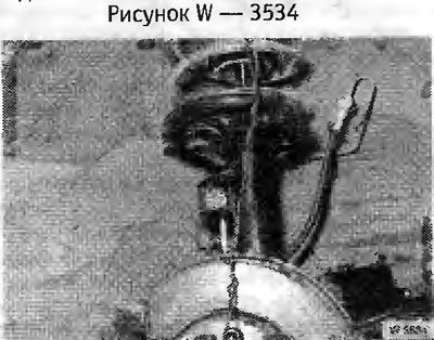
Screw in the wheel bolt and secure it to the wheel bolt and coil spring, see the picture. With this suspension, the hub will not fall off after the bolts are loosened.
Loosen bolt 2 of the ball joint until it rests against the shock absorber strut.
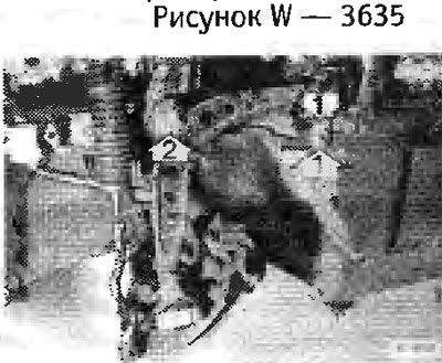
Unscrew the lower bolts "1" of the shock absorber strut. Clean the threaded holes with a wire brush.
Unscrew the centering bolt "2", while marking the position of the spacer washers (on both sides) for their subsequent installation.
Press out the ball joint with a suitable puller, for example HAZET 779.
Remove bolts "1" from the bottom.
From the top side, unscrew the nut of the ball joint "2" on the bridge beam. Knock out the ball joint with a plastic hammer. Remove the transverse arm.
Before installing the wishbone, thoroughly wash and degrease the ball joint necks and corresponding receiving holes with solvent.
Be sure to replace the self-locking nuts.
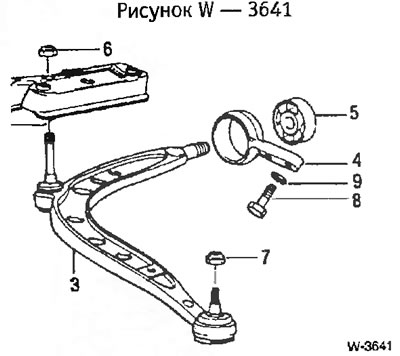
Insert the transverse arm. To install the nut "6" on the front axle beam, press the transverse arm upwards from the ball joint with a jack. Use a wooden spacer for this.
Tighten bolts "8" and the new self-locking nut "6" to a torque of 50 Nm.
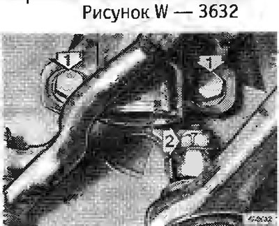
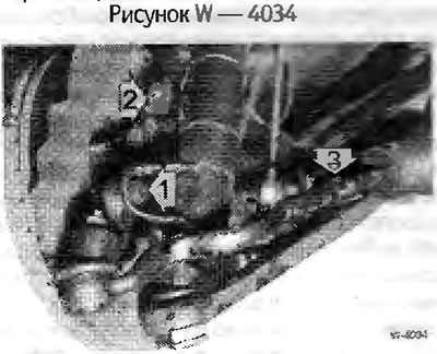
Insert the centering bolt "2" from below, while observing the correct installation position of the spacer washers (Figure W 4034). Screw on a new self-locking nut and tighten it to a torque of 110 Nm. (Figure W 3632) Tighten the shock absorber strut from below with new bolts with a tightening torque of 110 Nm. The bolts have a locking coating and must be replaced after each unscrewing.
Tighten the new self-locking nut "7" on the outer ball joint of the wishbone to a torque of 65 Nm (Figure W 3641). Remove the wire hanger.
Screw the wheel on, observing the markings made during removal. Lower the car and tighten the wheel bolts crosswise to a torque of 110 Nm.
Removal
Loosen the wheel bolts with the vehicle parked on the ground.
Mark the relative positions of the disc and the wheel hub with paint so that you can later install the balanced wheel in its original place.
Raise the car and remove the wheel.
Screw in the wheel bolt and secure it to the wheel bolt and coil spring, see the picture. With this suspension, the hub will not fall off after the bolts are loosened.
Loosen bolt 2 of the ball joint until it rests against the shock absorber strut.
Unscrew the lower bolts "1" of the shock absorber strut. Clean the threaded holes with a wire brush.
Unscrew the centering bolt "2", while marking the position of the spacer washers (on both sides) for their subsequent installation.
Press out the ball joint with a suitable puller, for example HAZET 779.
Remove bolts "1" from the bottom.
From the top side, unscrew the nut of the ball joint "2" on the bridge beam. Knock out the ball joint with a plastic hammer. Remove the transverse arm.
Installation
Before installing the wishbone, thoroughly wash and degrease the ball joint necks and corresponding receiving holes with solvent.
Be sure to replace the self-locking nuts.
Insert the transverse arm. To install the nut "6" on the front axle beam, press the transverse arm upwards from the ball joint with a jack. Use a wooden spacer for this.
Tighten bolts "8" and the new self-locking nut "6" to a torque of 50 Nm.
Insert the centering bolt "2" from below, while observing the correct installation position of the spacer washers (Figure W 4034). Screw on a new self-locking nut and tighten it to a torque of 110 Nm. (Figure W 3632) Tighten the shock absorber strut from below with new bolts with a tightening torque of 110 Nm. The bolts have a locking coating and must be replaced after each unscrewing.
Tighten the new self-locking nut "7" on the outer ball joint of the wishbone to a torque of 65 Nm (Figure W 3641). Remove the wire hanger.
Screw the wheel on, observing the markings made during removal. Lower the car and tighten the wheel bolts crosswise to a torque of 110 Nm.
This article is available at russian, bulgarian, belarusian, ukrainian, serbian, croatian, romanian, polish, slovak, hungarian
Article verified: Chebotarev Vladislav
Share information:
Previous articles
БМВ E36: Front and rear axle
Next articles
Similar articles on other types of BMW cars:
Removal and installation the transverse arm BMW 5 Series E39 (1995-2003)
Removal and installation the oil pan BMW 5 Series E12 (1972-1981)
Cylinder Head Cover — Removal and Installation BMW 7 Series E32 (1986-1994)
Pistons — removal and installation BMW X3 E83 (2003-2010)
Removal and installation the engine BMW X5 E53 (1999-2006)
Link in different formats to this page
Visitor comments
No comments yet
- General information
- Manual
- Maintenance
- Power unit
- Engine repair
- Cooling system
- Power system (gasoline)
- Injection system (gasoline)
- Fuel system (diesel)
- Exhaust system
- Ignition system
- Charge and launch systems
- Transmission
- Car gearbox
- Clutch and drive shafts
- Chassis
- Brake system
- Suspension front and rear
- Steering
- Body
- Body care and repair
- Exterior
- Interior
- Electrical equipment
- Troubleshooting
- Lighting and signaling
- Equipment and devices
- Heater and air conditioner
- Electrical circuits
- General information
- Manual
- Repair on the road
- Weekly checks
- Maintenance
- Troubleshooting
- Power unit
- 4 cylinder engines
- 6 cylinder engines
- Engine overhaul
- Cooling and heating
- Fuel and exhaust system
- Starting and charging system
- Ignition system
- Transmission
- Clutch
- Mechanical gearbox
- Automatic gearbox
- Cardan and drive shafts
- Chassis
- Brake system
- Wheel suspension
- Steering
- Body
- Exterior
- Interior
- Electrical equipment
- Equipment and devices
- Electrical circuits
- General information
- Maintenance
- Power unit
- Engine repair
- Cooling system
- Ignition system
- Supply system
- Fuel injection system
- Exhaust system
- Transmission
- Clutch
- Car gearbox
- Front and rear axle
- Chassis
- Steering
- Brake system
- Body
- Exterior
- Interior
- Electrical equipment
- Heating system
- Equipment and devices
- Power devices
- Electrical circuits
- Power unit
- M10/M20 engine
- M40 engine
- Ignition system
- Lubrication system
- Cooling system
- Supply system
- Fuel injection
- Exhaust system
- Transmission
- Clutch
- Manual gearbox
- Front axle
- Rear axle
- Chassis
- Steering
- Brake system
- Body
- Exterior
- Interior
- Electrical equipment
- Heating system
- Equipment and devices
- Electrical circuits
- General information
- Specifications
- Operation and maintenance
- 4-cylinder engine
- Engine repair
- Cooling and lubrication system
- Supply system
- Ignition system
- 6-cylinder engine
- Engine repair
- Cooling and lubrication system
- Supply system
- Fuel injection system
- Ignition system
- Transmission
- Clutch
- 4-speed manual gearbox
- 5-speed manual gearbox
- Automatic gearbox
- Cardan and rear axle
- Chassis
- Steering
- Front suspension
- Rear suspension
- Brake system
- Electrical equipment
- Equipment and devices
- Electrical circuits