
Table of contents: Cooling circuit diagram ↓ Elements of the cooling system ↓
- Home
- BMW 3 Series
- E46
- Power unit
- Cooling system
- Engine cooling system device
Engine cooling system device (BMW 3 Series E46)
Cooling circuit diagram
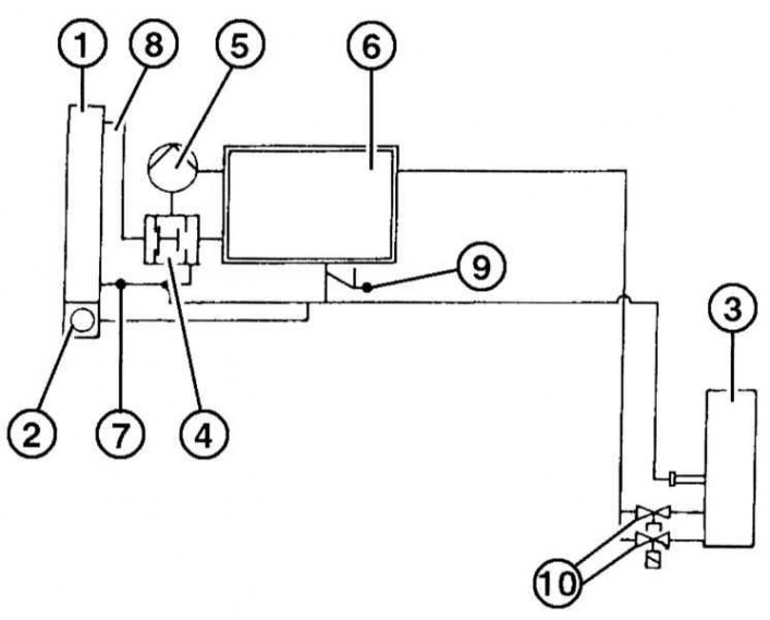
1 — radiator
2 - expansion tank
3 - interior heating
4 - thermostat
5 - coolant pump
6 — cylinder block
7 - return
8 - serve
9 — throttle valve heating
10— heater tap
Elements of the cooling system
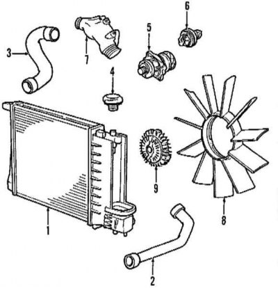
1 - radiator
2 - lower radiator hose
3 - Upper radiator hose
4 - radiator cap
5 - water pump
6 - thermostat
7 - thermostat housing
8 — radiator fan impeller
9 - viscous coupling
The engine is equipped with a circulation cooling system. Until the engine is warmed up, the coolant circulates only in the cylinder head and block and, with the heater tap open, in the heat exchanger of the interior heater. As the coolant temperature increases, the thermostat opens a large cooling circuit. The coolant is directed through the radiator by a constantly running pump. There is an innovation in gasoline engines, which consists of the so-called cooling by characteristics. In this case, the engine management system regulates the opening temperature of the thermostat and thus optimizes the engine temperature according to the fuel consumption criterion.
The coolant is poured through an expansion tank, which is located on the side of the radiator and serves as a container for the liquid. It compensates for the expansion of the liquid that occurs due to its heating and allows it to decrease in volume after the engine cools down.
To improve cooling efficiency, the system is equipped with a temperature-controlled fan. When the coolant temperature rises to +93°C, the thermal switch turns on the fan via a relay. If the coolant temperature drops below +89°C, the thermal switch turns off the fan again.
The radiator fan may turn on when the engine is not running. Due to the presence of heat stagnation in the engine compartment, this can happen many times. Therefore, when performing work in the fan area, wait until the engine cools down.
320i, 323i, 328i with air conditioning: To increase the cooling efficiency, an additional impeller is installed on the coolant pump shaft. A viscous coupling is located in the hub. As soon as the air coming from the radiator reaches a temperature of +90°C, a bimetallic plate in the viscous coupling connects the fan. The fan rotates at engine speed and provides the required air flow until the cooling air temperature drops to +60°C. After this, the viscous coupling switches off and reduces the fan speed. Due to the fan not working constantly, the useful engine power increases and fuel consumption decreases.
This article is available at russian, bulgarian, belarusian, ukrainian, serbian, croatian, romanian, polish, slovak, hungarian
Article verified: Sevastyanov Nikolay
Share information:
Previous articles
БМВ E46: Cooling system
Next articles
Similar articles on other types of BMW cars:
Engine cooling system parts BMW 5 Series E12 (1972-1981)
Diagnostics of engine cooling system faults BMW 5 Series E34 (1988-1996)
Diagnostics of engine cooling system faults BMW 7 Series E32 (1986-1994)
Replacing the sensors of the engine management system BMW 7 Series E38 (1994-2001)
Cooling system — equipment and tools BMW X3 E83 (2003-2010)
Engine cooling system — design description BMW X5 E53 (1999-2006)
Link in different formats to this page
Visitor comments
No comments yet
- General information
- Manual
- Maintenance
- Power unit
- Engine repair
- Cooling system
- Power system (gasoline)
- Injection system (gasoline)
- Fuel system (diesel)
- Exhaust system
- Ignition system
- Charge and launch systems
- Transmission
- Car gearbox
- Clutch and drive shafts
- Chassis
- Brake system
- Suspension front and rear
- Steering
- Body
- Body care and repair
- Exterior
- Interior
- Electrical equipment
- Troubleshooting
- Lighting and signaling
- Equipment and devices
- Heater and air conditioner
- Electrical circuits
- General information
- Manual
- Repair on the road
- Weekly checks
- Maintenance
- Troubleshooting
- Power unit
- 4 cylinder engines
- 6 cylinder engines
- Engine overhaul
- Cooling and heating
- Fuel and exhaust system
- Starting and charging system
- Ignition system
- Transmission
- Clutch
- Mechanical gearbox
- Automatic gearbox
- Cardan and drive shafts
- Chassis
- Brake system
- Wheel suspension
- Steering
- Body
- Exterior
- Interior
- Electrical equipment
- Equipment and devices
- Electrical circuits
- General information
- Maintenance
- Power unit
- Engine repair
- Cooling system
- Ignition system
- Supply system
- Fuel injection system
- Exhaust system
- Transmission
- Clutch
- Car gearbox
- Front and rear axle
- Chassis
- Steering
- Brake system
- Body
- Exterior
- Interior
- Electrical equipment
- Heating system
- Equipment and devices
- Power devices
- Electrical circuits
- Power unit
- M10/M20 engine
- M40 engine
- Ignition system
- Lubrication system
- Cooling system
- Supply system
- Fuel injection
- Exhaust system
- Transmission
- Clutch
- Manual gearbox
- Front axle
- Rear axle
- Chassis
- Steering
- Brake system
- Body
- Exterior
- Interior
- Electrical equipment
- Heating system
- Equipment and devices
- Electrical circuits
- General information
- Specifications
- Operation and maintenance
- 4-cylinder engine
- Engine repair
- Cooling and lubrication system
- Supply system
- Ignition system
- 6-cylinder engine
- Engine repair
- Cooling and lubrication system
- Supply system
- Fuel injection system
- Ignition system
- Transmission
- Clutch
- 4-speed manual gearbox
- 5-speed manual gearbox
- Automatic gearbox
- Cardan and rear axle
- Chassis
- Steering
- Front suspension
- Rear suspension
- Brake system
- Electrical equipment
- Equipment and devices
- Electrical circuits