
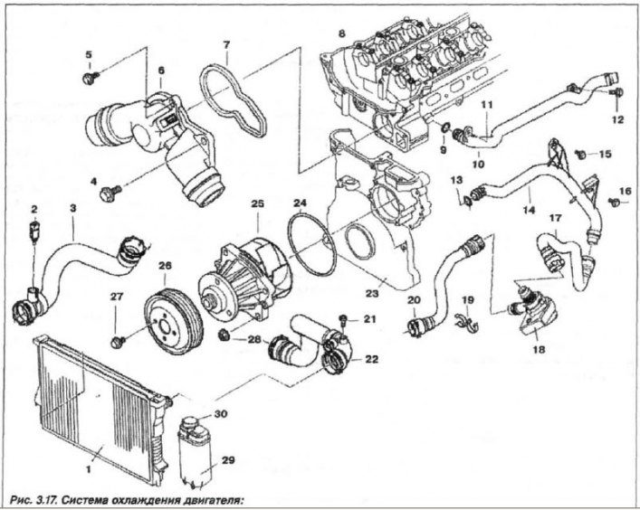
1 - radiator; 2 - temperature sensor; 3, 17, 20, 22 - hose; 5 - bolt (M6x25); 6 - thermostat in the housing; 7 - gasket; 3 - cylinder head; 9, 13 - ring (20x3); 10 - heating hose; 11 - nut (M6); 12, 15, 16 - bolt; 14 - pipeline; 18 - heating pump; 19 - holder; 21 - Air bleed screw; 23 - timing belt cover; 24 - ring (68x5); 25 - engine pump; 26 - pulley; 27 - bolt (M6x16); 28 - Nut (MB); 29 - expansion tank; 30 - tank cap
The cooling system is shown in Fig. 3.17 and includes:
- cooling jackets (cylinder heads and blocks);
- aluminum cross flow radiator;
- coolant pump;
- additional heating and ventilation system pump with electric drive;
- thermostat;
- coolant pump drive belt;
- expansion tank;
- nine blade fan with flexible coupling;
- heat exchanger of heating and ventilation system;
- coolant temperature sensor;
- coolant.
When installing an air conditioner on certain vehicle modifications, an additional electric fan is used.
Safety precautions when working with coolant
- When working on the cooling system, there is a risk of burns from coolant vapors; all work should only be performed on a cooled engine. Open the cooling system only when the engine has cooled.
- When working with oil, fuel and coolant circuits, the generator must be protected from possible contamination.
- The coolant is toxic, avoid contact with exposed skin, mucous membranes of the respiratory tract and eyes. Rinse damaged areas with plenty of running water and seek medical attention. The drained liquid cannot be reused, send it for disposal.
Cooling system leak test pressure is 1.5 kgf/cm². Engine cooling system capacity, including body cabin heater, is 9.8 l. Coolant replacement frequency is every 2 years of operation.