
- Home
- BMW 7 Series
- E38
- Chassis
- Brake system
- Removal and installation of hydraulic modulator of ABS / ASC+T / DSC systems
Removal and installation of hydraulic modulator of ABS / ASC+T / DSC systems (BMW 7 Series E38)
1. Turn off the ignition and disconnect the negative cable from the battery.
2. Pump out the brake fluid from the brake master cylinder reservoir.
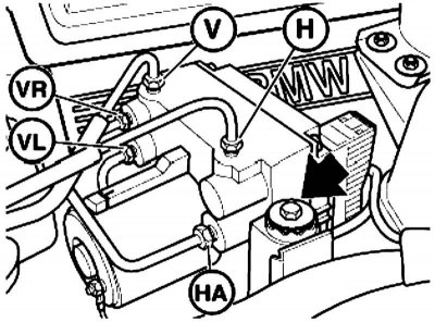
V (front wheels) — from the two-cavity GTZ of circuit V to the hydraulic modulator of circuit V (front wheel brake drive circuit)
H (rear wheels) — from the two-cavity GTZ of the H circuit to the hydraulic modulator of the H circuit (rear wheel brake drive circuit)
VR (right front wheel) — from the VR hydraulic modulator to the VR brake mechanism
VL (left front wheel) — from the VL hydraulic modulator to the VL brake mechanism
HR (right rear wheel) — from the HR hydraulic modulator to the HR brake mechanism
HL (left rear wheel) — from the HL hydraulic modulator to the HL brake mechanism
HA (rear axle) - from the HA hydraulic modulator to the rear wheel brake mechanism
1 - Membrane damper of the outlet channel
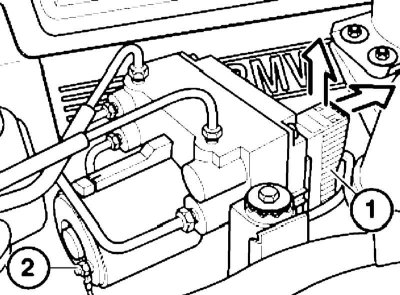
1. Disconnect the central connector (1), loosen the nut (2) and disconnect the ground cable.
2. Disconnect the brake pipes, unscrew the bolt and remove the hydraulic modulator. If necessary, mark the pipes to avoid confusion during installation.
3. Installation is carried out in the reverse order. Finally, bleed the brake system.
V (front wheels) — from the two-cavity GTZ of circuit V to the hydraulic modulator of circuit V (front wheel brake drive circuit)
H (rear wheels) — from the two-cavity GTZ of the H circuit to the hydraulic modulator of the H circuit (rear wheel brake drive circuit)
VR (right front wheel) — from the VR hydraulic modulator to the VR brake mechanism
VL (left front wheel) — from the VL hydraulic modulator to the VL brake mechanism
HR (right rear wheel) — from the HR hydraulic modulator to the HR brake mechanism
HL (left rear wheel) — from the HL hydraulic modulator to the HL brake mechanism
HA (rear axle) - from the HA hydraulic modulator to the rear wheel brake mechanism
1 - Membrane damper of the outlet channel
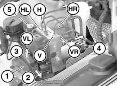
1. Unlock the connector lock (1) in direction (2) and disconnect the connector by pulling it vertically upwards in direction (3). Disconnect the brake pipes, marking them first if necessary to avoid confusion during installation.
2. On models with DSC unlock and disconnect the connector (4) from the pressure sensor.
3. Unscrew the bolt (5) and remove the hydraulic modulator, avoiding bending or deformation of the brake pipes.
4. Installation is carried out in the reverse order. Finally, bleed the brake system.
V (front wheels) — from the two-cavity GTZ of circuit V to the hydraulic modulator of circuit V (front wheel brake drive circuit)
H (rear wheels) — from the two-cavity GTZ of the H circuit to the hydraulic modulator of the H circuit (rear wheel brake drive circuit)
VR (right front wheel) — from the VR hydraulic modulator to the VR brake mechanism
VL (left front wheel) — from the VL hydraulic modulator to the VL brake mechanism
HR (right rear wheel) — from the HR hydraulic modulator to the HR brake mechanism
HL (left rear wheel) — from the HL hydraulic modulator to the HL brake mechanism
HA (rear axle) - from the HA hydraulic modulator to the rear wheel brake mechanism
1 - Membrane damper of the outlet channel
1. Disconnect the central connector (1 on illustrations), loosen the nut (2) and disconnect the ground cable.
2. Disconnect the brake pipes, unscrew the bolt (see illustration Brake pipes and ABS hydraulic modulator mounting bolt) and remove the hydraulic modulator. If necessary, mark the tubes to avoid confusion during installation.
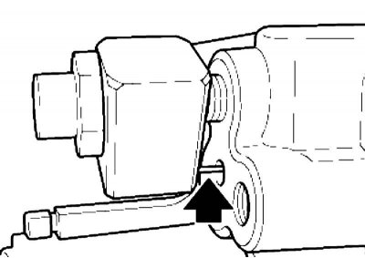
3. Installation is carried out in the reverse order. Make sure that the diaphragm damper of the outlet channel is installed correctly: the pin must enter the hole. Finally, bleed the brake system.
The text is based on materials from the website: «BMWMAN.ru»
2. Pump out the brake fluid from the brake master cylinder reservoir.
ABS hydraulic modulator Brake pipes and mounting bolt for ABS hydraulic modulator
V (front wheels) — from the two-cavity GTZ of circuit V to the hydraulic modulator of circuit V (front wheel brake drive circuit)
H (rear wheels) — from the two-cavity GTZ of the H circuit to the hydraulic modulator of the H circuit (rear wheel brake drive circuit)
VR (right front wheel) — from the VR hydraulic modulator to the VR brake mechanism
VL (left front wheel) — from the VL hydraulic modulator to the VL brake mechanism
HR (right rear wheel) — from the HR hydraulic modulator to the HR brake mechanism
HL (left rear wheel) — from the HL hydraulic modulator to the HL brake mechanism
HA (rear axle) - from the HA hydraulic modulator to the rear wheel brake mechanism
1 - Membrane damper of the outlet channel
1. Disconnect the central connector (1), loosen the nut (2) and disconnect the ground cable.
Do not allow brake fluid to enter electrical wiring connectors.
2. Disconnect the brake pipes, unscrew the bolt and remove the hydraulic modulator. If necessary, mark the pipes to avoid confusion during installation.
3. Installation is carried out in the reverse order. Finally, bleed the brake system.
ABS/ASC T hydraulic modulator, DSC3 (since 09.1998 issue.) Brake pipes and connectors for ABS/ASC T, DSC3 hydraulic modulator
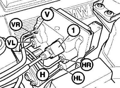
V (front wheels) — from the two-cavity GTZ of circuit V to the hydraulic modulator of circuit V (front wheel brake drive circuit)
H (rear wheels) — from the two-cavity GTZ of the H circuit to the hydraulic modulator of the H circuit (rear wheel brake drive circuit)
VR (right front wheel) — from the VR hydraulic modulator to the VR brake mechanism
VL (left front wheel) — from the VL hydraulic modulator to the VL brake mechanism
HR (right rear wheel) — from the HR hydraulic modulator to the HR brake mechanism
HL (left rear wheel) — from the HL hydraulic modulator to the HL brake mechanism
HA (rear axle) - from the HA hydraulic modulator to the rear wheel brake mechanism
1 - Membrane damper of the outlet channel
1. Unlock the connector lock (1) in direction (2) and disconnect the connector by pulling it vertically upwards in direction (3). Disconnect the brake pipes, marking them first if necessary to avoid confusion during installation.
2. On models with DSC unlock and disconnect the connector (4) from the pressure sensor.
3. Unscrew the bolt (5) and remove the hydraulic modulator, avoiding bending or deformation of the brake pipes.
4. Installation is carried out in the reverse order. Finally, bleed the brake system.
Hydromodulator ABS/ASC T, DSC1, DSC2, DSC3 (until 09.1998.) Brake pipes and connectors of the ABS/ASC T, DSC1, DSC2, DSC3 hydraulic modulator
V (front wheels) — from the two-cavity GTZ of circuit V to the hydraulic modulator of circuit V (front wheel brake drive circuit)
H (rear wheels) — from the two-cavity GTZ of the H circuit to the hydraulic modulator of the H circuit (rear wheel brake drive circuit)
VR (right front wheel) — from the VR hydraulic modulator to the VR brake mechanism
VL (left front wheel) — from the VL hydraulic modulator to the VL brake mechanism
HR (right rear wheel) — from the HR hydraulic modulator to the HR brake mechanism
HL (left rear wheel) — from the HL hydraulic modulator to the HL brake mechanism
HA (rear axle) - from the HA hydraulic modulator to the rear wheel brake mechanism
1 - Membrane damper of the outlet channel
1. Disconnect the central connector (1 on illustrations), loosen the nut (2) and disconnect the ground cable.
Do not allow brake fluid to enter electrical wiring connectors.
2. Disconnect the brake pipes, unscrew the bolt (see illustration Brake pipes and ABS hydraulic modulator mounting bolt) and remove the hydraulic modulator. If necessary, mark the tubes to avoid confusion during installation.
3. Installation is carried out in the reverse order. Make sure that the diaphragm damper of the outlet channel is installed correctly: the pin must enter the hole. Finally, bleed the brake system.
The text is based on materials from the website: «BMWMAN.ru»
This article is available at russian, bulgarian, belarusian, ukrainian, serbian, croatian, romanian, polish, slovak, hungarian
Article verified: Polikarpov Saveliy
Share information:
Previous articles
БМВ E38: Brake system
Next articles
Similar articles on other types of BMW cars:
Camshafts, rocker arms and hydraulic supports — removal and… BMW 3 Series E46 (1998-2006, petrol)
Removal and installation the contact ignition distributor BMW 3 Series E21 (1975-1983)
Description, removal and installation of the brake system vacuum… BMW 5 Series E28 (1981-1988)
Removal and installation the oil pan BMW 5 Series E12 (1972-1981)
Pistons — removal and installation BMW X3 E83 (2003-2010)
Removal and installation of the module of the systems in the airbag… BMW X5 E53 (1999-2006)
Link in different formats to this page
Visitor comments
No comments yet
- General information
- Introduction to guide
- Manual
- Maintenance
- Power unit
- Engine M60/1, M60/2 (petrol)
- M62 engine (petrol)
- M57 engine (diesel)
- M67 engine (diesel)
- Cooling system
- Fuel system (petrol)
- Fuel system (diesel)
- Exhaust system
- Ignition and control systems
- Charge and launch systems
- Transmission
- Clutch
- Mechanical gearbox
- Automatic gearbox
- Cardan and drive shafts
- Chassis
- Brake system
- Front suspension
- Rear suspension
- Steering
- Body
- Exterior
- Interior
- Electrical equipment
- Equipment and devices
- Lighting
- Heating and air conditioning
- Electrical circuits
- General information
- Care and maintenance
- Power unit
- Minor engine repair
- Engine overhaul
- Lubrication system
- Cooling system
- Ignition system
- Supply system
- Injection system (petrol)
- Injection system (diesel)
- Exhaust system
- Transmission
- Clutch
- Manual gearbox
- Automatic gearbox
- Cardan gear
- Rear axle and shafts
- Chassis
- Front suspension
- Rear suspension
- Steering
- Wheels and tires
- Brake system
- Body
- Body elements
- Electrical equipment
- Equipment and devices
- Electrical circuits