
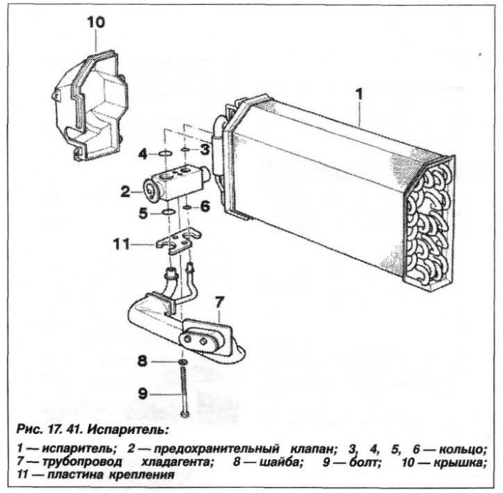
Attention! When removing, avoid deformation of the evaporator radiator fins. If necessary, clean and straighten them using plate feeler gauges.
The design of the evaporator is shown in Figure 17.41.
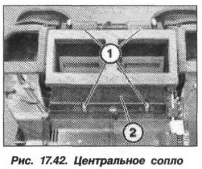
The air conditioning system evaporator must be removed in the following order. The air conditioning control unit is removed. Release the clamps (1, Fig. 17.42) and remove the middle nozzle (2) for heating the glass.
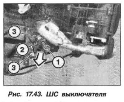
Disconnect the SS (1, Fig. 17.43) switch. Release the fan limit switch (2) from the clamps and remove it in the direction indicated by the arrow from the guide (3).
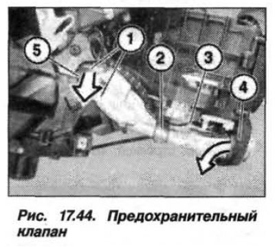
Remove the bolts (1, Fig. 17.44), unscrew the holder (2). Pull the safety valve (3) in the direction indicated by the arrow out of the flange (5) and remove it from the housing (4).
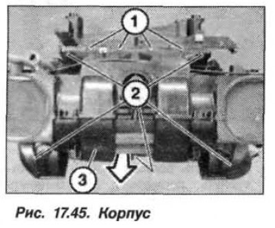
Release the clamps (1, Fig. 17.45), loosen the screws (2) and remove the fan housing (3) assembly in the direction indicated by the arrow. Loosen the screws and remove the bottom of the fan housing.
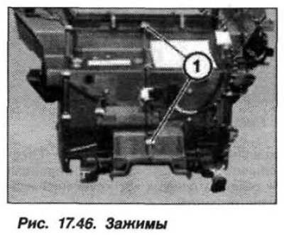
Release the clamps (1, Fig. 17.46) on the fan housing.
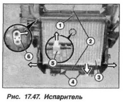
Remove the bolt (1, Fig. 17.47) and release the clamps (2) of the fan housing. Pull both halves (4) of the fan housing in different directions and push the flange (6) in the direction indicated by the arrow out of the hole in the housing. Release the temperature sensor holder (5) from the clamps and remove it in the direction indicated by the arrow from the evaporator (3). Remove the evaporator in the direction indicated by the arrow from the fan housing.
The installation of the air conditioning system evaporator should be carried out in the reverse order, while it is necessary to pay attention to the sufficiency of the length of the temperature sensor wires inside the housing and the correct position of both halves (4) of the housing and the flange for installing the safety valve. Replace the sealing rings of the safety valve.