
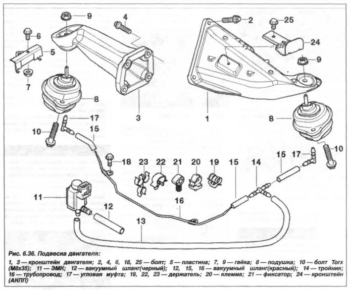
Disconnect the jumper (1, Fig. 6.128) ground connection from the engine support bracket. Loosen the bolts (2) and unscrew the nut (3) securing the bracket. Disconnect the right engine support bracket from the cylinder block and remove it. Install the right engine support bracket in the reverse order, and it is necessary to. Clean the contact surfaces to ensure a reliable connection of the jumper to the ground.

Tighten the bolts (2) M8 (8.8) securing the bracket to the engine to a torque of 19.0 N·m (1.90 kgf·m). Tighten the nut (3) M10 (10.9) securing the bracket to the beam to a torque of 56.0 N·m (5.60 kgf·m). Install the removed components.
After completing the engine installation, check their tightening.
The left engine support bracket must be removed in the following order. Prepare the "00.0.200" device and disconnect the "-" terminal from the battery. Raise the engine by 5 mm using the "00.0.200" device. Remove the engine auxiliary protection panel and the stiffening plate. Remove the left engine compartment screen and disconnect the shock absorber from the oil pressure sensor.
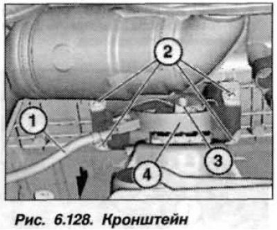
Unscrew the nut (1. Fig. 6.129) fastening the engine bracket to the body.
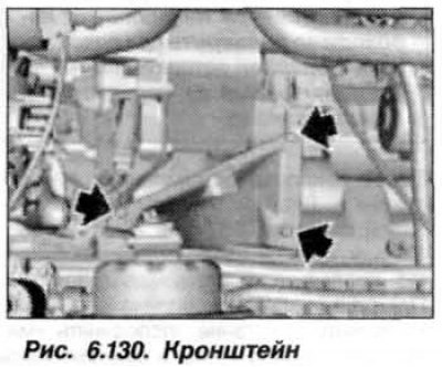
Remove the bolts (arrows, Fig. 6.130) and disconnect the bracket (1) of the left engine support from the engine cylinder block.
The left engine mount bracket should be installed in the reverse order, and it is necessary. Tighten the bolts (1) M8 (8.8) securing the bracket to the engine to a torque of 19.0 N·m (1.90 kgf·m). Tighten the nut (1) M10 (10.9) securing the bracket to the beam to a torque of 56.0 N·m (5.60 kgf·m). Install the removed components. After completing the engine installation, check their tightening.