
Remove the screws (2, see Fig. 5.186) and remove the cover (1) of the control electronics compartment.
Note: Unscrew the sealing gasket screws in the mount only when dismantling the wiring harness.
Unlock and disconnect the loops on the DME and Valvetronic control units. Remove the Valvetronic control unit and the integrated power supply module. Lift the power supply module, unlock and disconnect the loop on the bottom. Remove the control unit. Unlock and disconnect the loop from the control electronics compartment fan.
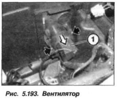
Unlock and disconnect the relay. Loosen the bolts on the ECU bracket and remove the bracket by moving it upwards. Loosen the bolts (arrows, Fig. 5.193) and remove the fan (1) of the control electronics compartment in the direction indicated by the arrow.
When installing the fan, make sure that the cover clicks into place. Check the operation of the DME system and erase the information from the fault memory.
[The original material is located on the website: «BMWMAN»]