
In addition, the driving and driven gears have a marking of selection to each other ("P") for noise and contact, applied with an electric pencil (marking "602" in the photo). The deviation of the actual distance between the end of the driving gear and the differential axis ("e". See the figure) from the nominal value is also marked on the driving gear with a "+" or "-" sign (marking "15" in the photo).
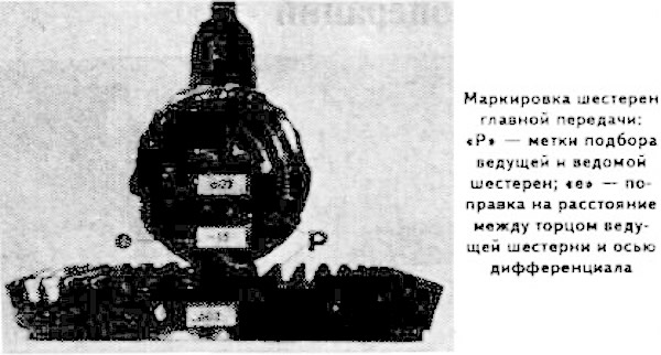
The "+" sign indicates that the correction to the nominal value "E" on the drive gear should be added to the actual distance between the end of the drive gear and the differential axis. And the "-" sign indicates that it should be subtracted from the actual value of the distance "E". The value of "e" ("-15" in the photo) is indicated in hundredths of a millimeter.
Press the outer bearing rings of the drive pinion into the sockets of the rear axle housing.
Install washer "A" on the drive gear (see picture) adjustment of the distance between the end of the drive gear and the differential axle with a thickness of 4.05 mm (the chamfer of the inner diameter of the washer must be directed towards the gear).
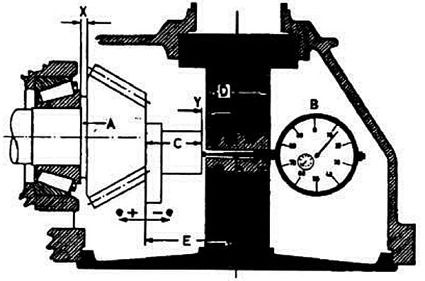
Device for adjusting the distance between the end of the drive gear and the differential axle:
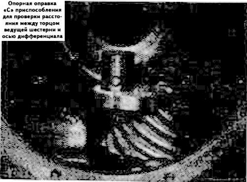
A - adjustment ring (X - ring thickness); B — indicator readings (Y — distance measured by the indicator); C, D — devices for measuring the distance between the end of the drive gear and the differential axis; E — distance between the end of the drive gear and the differential axis; "+e", "—e" — deviation of the actual distance between the end of the drive gear and the differential axis from the nominal value, stamped on the front end of the drive gear.
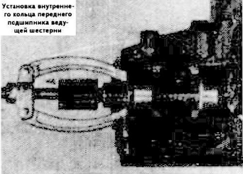
Using a mandrel of the required size, press the inner race of the rear bearing onto the drive gear until it stops against the adjusting washer.
Working from inside the axle housing, insert the pinion gear and press the front bearing inner race onto it using Kukko tools 22/1 and 6057 (see photo).
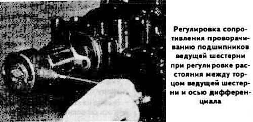
Install the pinion flange without the seal.
Tighten the drive gear flange nut until the bearing turning resistance moment is 22±1 kgf·cm.
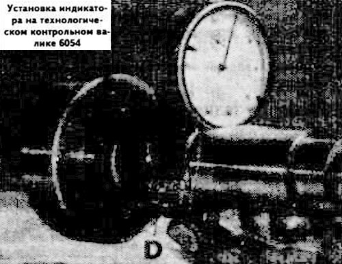
Measure the height of "C" (see picture) support mandrel, which in the example below is 38 mm, and install the mandrel on the end of the drive gear.
Measure the diameter "D" of the control shaft 6054 (in the photo: 40 mm). Fix the indicator on the control shaft, selecting the indicator leg stroke at 4 mm, and set the indicator arrow to zero.
When calculating the thickness of the washer for adjusting the distance between the end of the drive gear and the differential axis, the measured diameter "D" of the control shaft is taken, divided by 2, i.e. in our example 0=40:2=20 mm.
Install the 6054 measuring device with indicator into the rear axle housing, resting its leg against the support mandrel "C" (see adjustment diagram).
Take the "B" reading on the indicator, thereby determining the "Y" dimension.
Determine the thickness "X" of the adjusting washer "A" depending on the value "e" (indicated on the end of the drive gear) deviations from the nominal value of the distance "E" between the end of the pinion and the differential axis, which is 59.00 mm for the Gleason main gear and 61.85 mm for the Klingelnberg main gear.